Make: Electronics (64 page)
Authors: Charles Platt

Upgrade 2: Keypad Deactivation
This is now really simple. You can substitute a latching relay instead of the switch, S1, on the alarm box (shown in Figure 3-110), and use a keypad to set and reset the relay in exactly the same way as in the combination lock in
Experiment 20
. You’ll have to run an additional three wires from the relay, out of the alarm box, to the keypad (one supplying power to the “on” relay coil, another supplying power to the “off” coil, the third being a common ground). You can either use a 9-volt battery to power the electronics in association with the keypad, or run an additional fourth wire from the alarm box, to carry positive power to the logic chips, bearing in mind that you have to insert a voltage regulator at some point, to drop the 12 volts that the alarm uses to the 5 volts that the logic gates require. As the gates consume so little power, the 12-to-5 drop should be OK for the voltage regulator; it won’t have to dissipate too much heat.
With this additional feature, you can use the alarm like this:
- Press the pound key on the keypad to flip the latching relay into its “on” mode, so that it passes power to the alarm box, which is now armed.
- If you want to leave the house, push the button on the delay unit to give you 30 seconds in which to do so.
- If the alarm is triggered, enter your secret code on the keypad to deactivate it by flipping the latching relay to its “off” position and cutting power to the alarm box.
These modifications are so simple that I think the block diagram in Figure 4-114 should be all you need. I don’t think I need to give you any schematics. The only change you have to make to the existing alarm is to substitute the latching relay for the on/off switch.
But, there is still one obvious necessary enhancement needed: how can you get back into the house without instantly triggering the alarm?
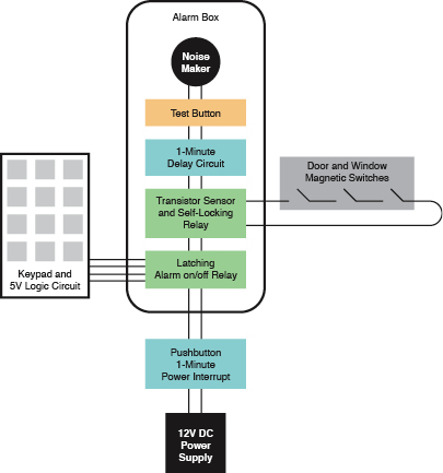
Figure 4-114.
This block diagram shows the relative placement of the old and new components. The pushbutton power interrupt (which allows you to leave the house before the alarm switches itself back on) goes between the power supply and everything else.
The latching relay substitutes for the DPDT switch on the previous version of the alarm. The transistor and self-locking relay, connected with the door and window magnetic switches, remain unchanged. The new delay circuit is inserted between the self-locking relay and the noisemaker. The test button is wired with the latching relay in the same way that it was wired previously with the DPDT switch.
Upgrade 3: Delay Before Deactivation
Typically, alarms include another delay feature. When you open a door on your way into the building and it triggers the alarm, you have 30 seconds to deactivate it, before it starts making a noise.
How can we implement this delay feature? If I try to use another 555 timer to generate a pulse to inhibit the noise, that won’t work, because the output from either the transistor or the relay can continue indefinitely. The relay locks itself on, and the transistor can continue passing voltage for as long as someone leaves a door open. If either of these signals activates a timer in monostable mode, the pulse from the timer will never end, and it will suppress the alarm indefinitely.
I think what I have to do is use a resistor and a capacitor to create a delay. I’ll power them through the existing relay, so that I can be sure that they’ll receive the full voltage of the power supply, after beginning from zero. Gradually the capacitor will acquire voltage—but I can’t connect this directly to the noisemaker, because the noisemaker will gradually get louder as the voltage increases.
I have to insert a device that will be triggered to give full voltage when the input rises past a certain point. To do this, I’ll use a 555 timer that’s wired in bistable mode. This kind of modification is generally known as a “kludge,” because it’s not elegant, uses too many components, and does not use them appropriately. What I really need is a comparator, but I don’t have space to get into that topic. So, using the knowledge that you have so far, the schematic in Figure 4-115 shows how a delay can be added to the alarm—not elegantly, but reliably.
The only problem is that if you power up a 555 timer in bistable mode, there’s a 50-50 chance that the timer starts itself with its output high or low. So I need to pull the voltage low on the reset pin (to start the timer with its output inhibited) and gradually let it become positive (to permit the output). At the same time, I want to start with the voltage high on the trigger pin and gradually lower it, until it falls below 1/3 of the power supply and triggers the output.
So there are two timing circuits. The one for the reset pin works faster than the one on the trigger pin, so that at the point when the timer is triggered, the reset won’t stop it.
The schematic shows component values that will do this. The 10 µF capacitor starts low but is charged through the 10K resistor in a couple of seconds. The timer is now ready to be triggered. But the 68 µF capacitor starts high (being connected with the positive side of the power supply) and takes a full minute to be pulled down to 1/3 of supply voltage through the 1M resistor. At that point, its voltage is low enough to trigger the 555. The timer output goes high and supplies the noisemaker.
You should be able to insert this little delay module in your alarm box, between the output from the relay and the input to the noisemaker without too much trouble. And if you want to adjust the delay, just use a higher or lower value resistor than 1M.
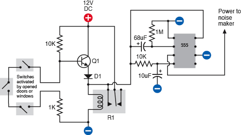
Figure 4-115.
This addition to the original alarm circuit imposes a one-minute delay before the alarm sounds. The 555 timer (wired in bistable mode) receives power through relay R1. The lower timing circuit initially applies negative voltage to the reset, ensuring that the 555 powers up with its output suppressed. This voltage quickly rises. Meanwhile the upper timing circuit applies a voltage to the trigger that gradually diminishes as the 68 µF capacitor equalizes its charge through the 1M resistor. When the voltage diminishes to 1/3 of the supply, the timer’s output goes high and starts the noisemaker. If the power to the circuit is interrupted at any time before this, the relay relaxes, the capacitors gradually discharge, and the alarm does not sound.
The Wrap-Up
If you add these three enhancements, your alarm will have all the features on my original wish list. Of course, if I were designing it from scratch, with all the information that has been added in this chapter of the book, it could be more elegant. But the modifications have not entailed making destructive changes to our original project, and all the design goals have been met.
5.
What Next?
At this point, we can branch out in numerous directions. Here are some possibilities:
Audio electronics
This is a field in itself, including hobby projects, such as simple amplifiers and “stomp boxes,” to modify guitar sound.
Radio-frequency devices
Anything that receives or transmits radio waves, from an ultra-simple AM radio to remote controllers.
Motors
The field of robotics has encouraged the growth of many online sites selling stepper motors, gear motors, synchronous motors, servo motors, and more.
Programmable microcontrollers
These are tiny computers on a single chip. You write a little program on your desktop computer, which will tell the chip to follow a series of procedures, such as receiving input from a sensor, waiting for a fixed period, and sending output to a motor. Then you download your program onto the chip, which stores it in nonvolatile memory. Popular controllers include the PICAXE, BASIC Stamp, Arduino, and many more. The cheapest ones retail for a mere $5 each.
Obviously, I don’t have space to develop all of these topics fully, so what I’m going to do is introduce you to them by describing just one or two projects in each category. You can decide which interests you the most, and then proceed beyond this book by reading other guides that specialize in that interest.
I’m also going to make some suggestions about setting up a productive work area, reading relevant books, catalogs, and other printed sources, and generally proceeding further into hobby electronics.
Shopping List: Experiments 25 Through 36
Tools
You won’t need any new tools for this section of the book.
Supplies and Components
As we have progressed to the point where you may want to pick and choose which projects you attempt, I will list the supplies and components at the beginning of each experiment.
Customizing Your Work Area
At this point, if you’re getting hooked on the fun of creating hardware but haven’t allocated a permanent corner to your new hobby, I have some suggestions. Having tried many different options over the years, my main piece of advice is this: don’t build a workbench!
Many hobby electronics books want you to go shopping for 2×4s and plywood, as if a workbench has to be custom-fabricated to satisfy strict criteria about size and shape. I find this puzzling. To me, the exact size and shape of a bench is not very important. I think the most important issue is storage.
I want tools and parts to be easily accessible, whether they’re tiny transistors or big spools of wire. I certainly don’t want to go digging around on shelves that require me to get up and walk across the room.
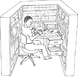
Figure 5-1.
The ideal work area: surrounded by storage. Never again will you need to get out of your chair!
This leads me to two conclusions:
1.
You need storage above the workbench.
2.
You need storage below the workbench.
Many DIY workbench projects allow little or no storage underneath. Or, they suggest open shelves, which will be vulnerable to dust. My minimum configuration would be a pair of two-drawer file cabinets with a slab of 3/4-inch plywood or a Formica-clad kitchen countertop placed across them. File cabinets are ideal for storing all kinds of objects, not just files.
Of all the workbenches I’ve used, the one I liked best was an old-fashioned steel office desk—the kind of monster that dates back to the 1950s. They’re difficult to move (because of their weight) and don’t look beautiful, but you can buy them cheaply from used office furniture dealers, they’re generous in size, they withstand abuse, and they last forever. The drawers are deep and usually slide in and out smoothly, like good file-cabinet drawers. Best of all, the desk has so much steel in it that you can use it to ground yourself before touching components that are sensitive to static electricity. If you use an antistatic wrist strap, you can simply attach it to a sheet-metal screw that you drive into one corner of the desk.
What will you put in the deep drawers of your desk or file cabinets? Some paperwork may be useful, perhaps including the following documents:
- Product data sheets
- Parts catalogs
- Sketches and plans that you draw yourself
The remaining capacity of each drawer can be filled with plastic storage boxes. The boxes can contain tools that you don’t use so often (such as a heat gun or a high-capacity soldering iron), and larger-sized components (such as loudspeakers, AC adapters, project boxes, and circuit boards). You should look for storage boxes that measure around 11 inches long, 8 inches wide, and 5 inches deep, with straight sides. Boxes that you can buy at Wal-Mart will be cheaper, but they often have tapering sides (which are not space-efficient).
The boxes that I like best are Akro-Grids, made by Akro-Mils (see Figures 5-2 and 5-3). These are very rugged, straight-sided, with optional transparent snap-on lids. You can download the full Akro-Mills catalog from
http://www.akro-mils.com
and then search online for retail suppliers. You’ll find that Akro-Mils also sells an incredible variety of parts bins, but I don’t like open bins because their contents are vulnerable to dust and dirt.

Figure 5-2.
Akro-Grid boxes contain grooves allowing them to be partitioned into numerous compartments for convenient parts storage.

Figure 5-3.
Lids are sold separately for Akro-Grid boxes to keep the contents dust-free. The height of the box in Figure 5-2 allows three to be stacked in a typical file-cabinet drawer. The box shown here allows two to be stacked.
For medium-size components, such as potentiometers, power connectors, control knobs, and toggle switches, I like storage containers measuring about 11 inches long, 8 inches wide, and 2 inches deep , divided into four to six sections. You can buy these from Michaels (the craft store), but I prefer to shop online for the Plano brand, as they seem more durably constructed. The Plano products that are most suitable for medium-size electronic parts are classified as fishing-tackle boxes, and you’ll see them at
http://www.planomolding.com/tackle/products.asp
.
For undivided, flat-format storage boxes, the Prolatch 23600-00 is ideally sized to fit a file-cabinet drawer, and the latches are sufficiently secure that you could stack a series of them on their long edges. See Figure 5-4.
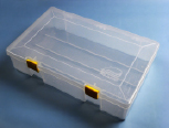
Figure 5-4.
This Plano brand box is undivided, making it useful for storing spools of wire or medium-size tools. When stacked upright on its long edge, three will fit precisely in a file-cabinet drawer.
Plano also sells some really nicely designed toolboxes, one of which you can place on your desktop. It will have small drawers for easy access to screwdrivers, pliers, and other basics. Because you need a work area that’s only about three feet square for most electronics projects, surrendering some desk space to a toolbox is not a big sacrifice.
If you have a steel desk with relatively shallow drawers, one of them can be allocated for printed catalogs. Don’t underrate the usefulness of hard copy, just because you can buy everything online. The Mouser catalog, for instance, has an index, which is better in some ways than their online search feature, and the catalog is divided into helpful categories. Many times I’ve found useful parts that I never knew existed, just by browsing, which is much quicker than flipping through PDF pages online, even with a broadband connection. Currently, Mouser is still quite generous about sending out their catalogs, which contain over 2,000 pages. McMaster-Carr will also send you a catalog, but only after you‘ve ordered from them, and only once a year.
Now, the big question: how to store all those dinky little parts, such as resistors, capacitors, and chips? I’ve tried various solutions to this problem. The most obvious is to buy a case of small drawers, each of which is removable, so you can place it on your desk while you access its contents. But I don’t like this system, for two reasons. First, for very small components, you need to subdivide the drawers, and the dividers are never secure. And second, the removability of the drawers creates the risk of accidentally emptying the contents on the floor. Maybe you’re too careful to allow this to happen, but I’m not!
My personal preference is to use Darice Mini-Storage boxes, shown in Figure 5-5. You can find these at Michaels in small quantities, or buy them more economically in bulk online from suppliers such as
http://www.craftamerica.com
. The blue boxes are subdivided into five compartments that are exactly the right size and shape for resistors. The yellow boxes are subdivided into ten compartments, which are ideal for semiconductors. The purple boxes aren’t divided at all, and the red boxes have a mix of divisions.

Figure 5-5.
Darice Mini-Storage boxes are ideal for components such as resistors, capacitors, and semiconductors. The boxes can be stacked stably or stored on shelves, with their ends labeled. The brand sticker is easily removed after being warmed with a heat gun.