Make: Electronics (79 page)
Authors: Charles Platt

Fundamentals
All about limit switches
The most obvious enhancement for your cart would be a better steering mechanism. You could use another motor to take care of this, with a pair of limit switches. Because limit switches are a basic, important idea in conjunction with motors, I’ll explain them in detail.
Figure 5-99 shows three successive views of a motor with an arm attached to it, which can press either a lower pushbutton or an upper pushbutton. Both of the pushbuttons are normally closed, but will open when pressed by the motor arm. These buttons are the limit switches. Typically you would use microswitches for this purpose, just like the ones that I suggested as barrier-sensors at the front of the cart.
In addition, there’s a DPDT relay that is activated by a simple on/off switch at the righthand side. On the cart, the 555 timer takes the place of the on/off switch, by feeding power to the relay.
Suppose that the motor begins with the arm pointing downward, as shown in the top view in Figure 5-99, and the motor is wired so that when it receives negative voltage at its lower terminal and positive at its upper terminal, it rotates counter-clockwise. This is what happens when the on/off switch closes and sends power to the DPDT relay. Positive voltage from the relay contacts cannot pass through the upper diode, but can pass through the upper limit switch, which is closed. Negative voltage cannot pass through the lower limit switch, because it’s open, but can pass through the lower diode. So, the motor starts to turn counterclockwise. During the midpoint of its arc, it receives power through both of the limit switches.
Finally, the motor arm reaches the upper switch, and opens it. This prevents positive voltage from reaching the motor through that switch, and the positive voltage is also blocked by the upper diode. So, at this time, the motor stops.
Now suppose that the on/off switch is opened, as in the top view in Figure 5-100. The relay loses its power, so its contacts relax. The voltage to the motor is now reversed. Negative voltage passes through the upper diode, while positive voltage reaches the motor through the lower limit switch. The motor starts running clockwise, until its arm hits the lower switch, opening it and cutting off power to the motor.
Limit switches are necessary, because if you continue to apply voltage to a simple DC motor that is unable to turn, the motor sucks more current, gets hot, and may burn out.
You can easily see how this kind of system could be used to control the cart’s steering. Even though the motor has only two positions, these are sufficient to make the cart turn when going backward, and proceed straight ahead when going forward.
To reduce power consumption, the DPDT relay could be replaced with a two-coil latching relay. The circuit would then have to be revised so that the relay is flipped to and fro by a pulse to each of its coils.
Fundamentals
All about limit switches (continued)
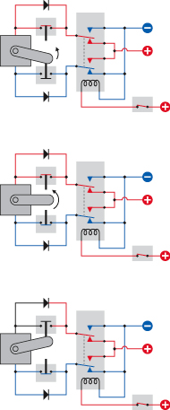
Figure 5-99.
The three diagrams, from top to bottom, show three snapshots of a motor controlled by a DPDT relay and two limit switches. When the on/off switch at bottom-right sends power to the relay, the lower relay contacts cause the motor to run counterclockwise until it stops itself as its arm opens the upper limit switch.
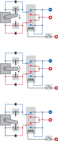
Figure 5-100.
When the on/off switch at bottom-right opens, the relay connects its upper contacts. This causes the motor to run clockwise until its arm opens the lower limit switch. Limit switches avoid the overheating and possible damage that are likely when power is delivered to a motor that is prevented from turning.
Fundamentals
All about motors
Brushed DC motor
This is the oldest, simplest design for an electric motor, shown in very simplified form in Figure 5-101. Coils are attached to a shaft where they can interact with stationary magnets around them. The magnetic attraction turns the shaft a little, at which point the next coil on the shaft is energized to turn the shaft a little more, and then the next coil—and so on. To make this happen, electricity has to be fed into the coils by “brushes,” often consisting of soft carbon pads that conduct power to a hub, known as a commutator, divided into sections, each of which is connected to a separate coil.
This basic design has several advantages if we want to build a small motorized gadget, such as a miniature robot or even a model airplane:
- Widely available
- Low cost
- Simple
- Reliable
- Will run in reverse when voltage reverses
In addition, brushed motors are often sold with reduction gearing built in. Such units are known as
gearhead motors
or
gear motors
. They free you from the need to use your own gears or belts to adjust the output speed yourself. You simply choose the motor that fits your specification.
DC stepper motor
This requires a controller, consisting of some electronics to tell the motor to rotate its shaft in small, discrete steps. The advantages of a stepper motor are:
- Precise positioning of the shaft
- Precise speed adjustment
Stepper motors are ideal for devices such as computer printers, where the paper has to roll up by a precise distance and the print head has to move laterally by an equally precise distance, but they are also useful in robots. If the motor is small enough to draw less than 200mA and will run on 12 volts or less, you can control it with pulses from a 555 timer. I’ll describe stepper motors in more detail in
Experiment 33
.
Servo motor
This is generally used in conjunction with a programmable microcontroller, which sends instructors to rotate the motor shaft to a specific position and then hold it there. I’ll mention servo motors when I introduce you to microcontrollers, but we won’t be dealing with them in detail.
Other types of motors exist, including brushless DC motors (which require a different type of controller and are found in computer disk drives and CD players), and AC motors (including synchronous motors, which synchronize their rotation with the frequency of AC voltage, and were used extensively in clocks, before clocks mostly became digital).
In this book, I’ll be talking mostly about brushed DC motors and DC stepper motors.
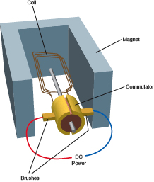
Figure 5-101.
The basic principle of a simple DC motor. The commutator passes electricity through a coil, creating a magnetic field that interacts with a magnet around the motor. The coil turns, and the commutator turns with it, until the electric field through the coil is reversed. This causes the process to repeat. In reality, a motor is likely to have a commutator formed from multiple segments, connected with multiple coils. The principle, however, remains the same.
Take-home messages from this experiment include the following:
- You can buy simple DC motors with reduction gearing built in, providing your choice of RPM. Literally hundreds of websites will sell you small motors for robotics projects.
- When you reverse the voltage to a DC motor, the motor runs in reverse.
- A DPDT relay can be wired so that when it closes its contacts, it reverses a power supply to a motor.
- You can use two limit switches and a pair of diodes to stop a motor at two positions. In each of its stopping positions, the motor consumes no power and you won’t have the risk of it burning out.
What other projects can you imagine using this simple set of techniques?
Mechanical Power
In the United States, the turning force, or torque, of a motor is usually measured in pound-feet or ounce-inches. In Europe, the metric system is used to measure torque in dynes.
A pound-foot is easy to understand. Imagine a lever pivoted at one end, as shown in Figure 5-102. If the lever is one foot long, and you hang a one-pound weight at the end of it, the turning force is one pound-foot.
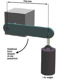
Figure 5-102.
The rotational force created by a motor is known as “torque,” and in the United States it is measured in pound-feet (or ounce-inches, for small motors). In the metric system, torque is measured in dynes. Note that the torque created by a motor will vary according to the speed at which the motor is running.
Fundamentals
Wire gauges
If you’re going to power larger motors, or other components that take more current than LEDs or small relays, you really need to know about wire gauges. In particular, what’s the relationship between wire thickness and AWG (American Wire Gauge)? And what gauge of wire should you use for any given current?
You can find numerous charts and tables if you go online, but many of these sources contradict each other, especially on the topic of how much current is safe to run through each gauge of wire.
After making several comparisons (and testing some wire samples myself), I’ve compiled the table in Figure 5-103, which I recommend as a compromise. Note the following:
- This table applies to solid-core copper wire.
- For stranded wire, or copper that has been tinned (giving it a silver appearance), the number of ohms per foot will
increase
, the number of feet per ohm will
decrease
, and the maximum amperage will
decrease
, probably by around 20%.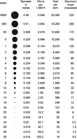
Figure 5-103.
American wire gauges (AWG) and their properties.
The maximum amperage assumes that the wire is insulated, preventing it from radiating heat as effectively as a bare conductor. I am also assuming that the wire is likely to be at least partially enclosed, inside a box or cabinet. At the amperages listed for each gauge of wire, you should expect the wire to become noticeably warm, and personally I would tend to use thicker wire instead of the maximums indicated in the table.
Most tables of this type only tell you the resistance of each gauge of wire in ohms per 1,000 feet. I have included that number but have also expressed the function the other way around, as the number of feet per ohm, as this doesn’t require you to do so much arithmetic with decimals.