Make: Electronics (66 page)
Authors: Charles Platt

The Art of Electronics, by Paul Horowitz and Winfield Hill (Cambridge University Press, Second Edition, 1989)
The fact that this book has been through 20 printings tells you two things: (1) Many people regard it as a fundamental resource; (2) Secondhand copies should be widely available, which is an important consideration, as the list price is over $100. It’s written by two academics, and has a more technical approach than
Practical Electronics for Inventors
, but I find it useful when I’m looking for backup information.
Getting Started in Electronics, by Forrest M. Mims III (Master Publishing, Fourth Edition, 2007)
Although the original dates back to 1983, this is still a fun book to have. I think I have covered many of its topics here, but you may benefit by reading explanations and advice from a completely different source, and it goes a little farther than I have into some electrical theory, on an easy-to-understand basis, with cute drawings. Be warned that it’s a brief book with eclectic coverage. Don’t expect it to have all the answers.
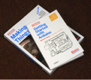
Figure 5-9.
These books from MAKE provide guidance if you want to go beyond basic microcontrollers into the more exotic realms of the Arduino chip.
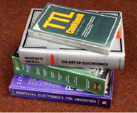
Figure 5-10.
A sun-damaged copy of the Don Lancaster’s classic TTL Cookbook, a 2,000-page catalog from the Mouser Electronics supply company, and two comprehensive reference books that can provide years of additional guidance in all areas of electronics.
Experiment 25: Magnetism
This experiment should be a part of any school science class, but even if you remember doing it, I suggest that you do it again, because setting it up takes only a matter of moments, and it’s going to be our entry point to a whole new topic: the relationship between electricity and magnetism. Quickly this will lead us into audio reproduction and radio, and I’ll describe the fundamentals of self-inductance, which is the third and final basic property of passive components (resistance and capacitance being the other two). I left self-inductance until last because it’s not very relevant to the experiments that you’ve done so far. But as soon as we start dealing with analog signals that fluctuate, it becomes essential.
You will need:
- Large screwdriver.
- 22-gauge wire (or thinner). Quantity: 6 feet.
- AA battery.
Fundamentals
A two-way relationship
Every electric motor that was ever made uses some aspect of the relationship between electricity and magnetism. It’s absolutely fundamental in the world around us. Remember that electricity can create magnetism:
When electricity flows through a wire, it creates a magnetic force around the wire.
The principle works in reverse: magnetism can create electricity.
When a wire moves through a magnetic field, it creates a flow of electricity in the wire.
This second principle is used in power generation. A diesel engine, or a water-powered turbine, or a windmill, or some other source of energy either turns coils of wire through a powerful magnetic field, or turns magnets amid some massive coils of wire. Electricity is induced in the coils. In the next experiment, you’ll see a dramatic mini-demo of this effect.
Procedure
This couldn’t be simpler. Wind the wire around the shaft of the screwdriver, near its tip. The turns should be neat and tight and closely spaced, and you’ll need to make 100 of them, within a distance of no more than 2 inches. To fit them into this space, you’ll have to make turns on top of previous turns. If the final turn tends to unwind itself (which will happen if you’re using stranded wire), secure it with a piece of tape. See Figure 5-11.
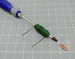
Figure 5-11.
Anyone who somehow missed this most basic childhood demo of electromagnetism should try it just for the fun of proving that a single AA battery can move a paper clip.
Now apply a battery, as shown in Figure 5-12. At first sight, this looks like a very bad idea, because you’re going to short out your battery just as you did in
Experiment 2
. But by passing the current through a wire that’s coiled instead of straight, we’ll get some work out of it before the battery expires.
Put a small paper clip near the screwdriver blade, on a soft, smooth surface that will not present much friction. A tissue works well. Because many screwdrivers are already magnetic, you may find that the paper clip is naturally attracted to the tip of the blade. If this happens, move the clip just outside the range of attraction. Now apply the 1.5 volts to the circuit, and the clip should jump to the tip of the screwdriver. Congratulations: you just made an electromagnet.

Figure 5-12.
A schematic can’t get much simpler than this.
Theory
Inductance
When electricity flows through a wire, it creates a magnetic field around the wire. Because the electricity “induces” this effect, it is known as
inductance
. The effect is illustrated in Figure 5-13.
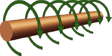
Figure 5-13.
When the flow of electricity is from left to right along this conductor, it induces a magnetic force shown by the green arrows.
The field around a straight wire is very weak, but if we bend the wire into a circle, the magnetic force starts to accumulate, pointing through the center of the circle, as shown in Figure 5-14. If we add more circles, to form a coil, the force accumulates even more. And if we put a magnetic object (such as a screwdriver) in the center of the coil, the effectiveness increases further.
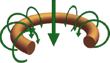
Figure 5-14.
When the conductor is bent to form a circle, the cumulative magnetic force acts through the center of the circle, as shown by the large arrow.
Here’s an approximated formula showing the relationship between the diameter of the coil, the width of the coil from end to end, the number of turns, and its inductance. The letter L is the symbol for inductance, even though the unit is the Henry, named after an American electrical pioneer named Joseph Henry:
L (in microHenrys) =
[(D × D) × (N x N)] / [(18 × D) + (40 × W)]
(Approximately)
In this formula, D is the diameter of the coil, N is the number of turns, and W is the width of the coil from end to end. See Figure 5-15. Here are three simple conclusions from this formula:
- Inductance increases with the diameter of the coil.
- Inductance increases with the square of the number of turns. (In other words, three times as many turns create nine times the inductance.)
- If the number of turns remains the same, inductance is lower if you wind the coil so that it’s slender and long, but is higher if you wind it so that it’s fat and short.
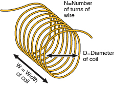
Figure 5-15.
The inductance of a coil increases with its diameter and with the square of its number of turns. If all other parameters remain the same, reducing the width (the distance from end to end) by packing the turns more tightly will increase the inductance.
