Make: Electronics (68 page)
Authors: Charles Platt

Here’s another thing to try. Disconnect the LED and connect a 100 μF electrolytic capacitor in series with signal diode, as shown in Figure 5-23. Attach your meter, measuring volts, across the capacitor. If your meter has a manual setting for its range, set it to 20V DC. Make sure the positive (unmarked) side of the diode is attached to the negative (marked) side of the capacitor, so that positive voltage will pass through the capacitor and then through the diode.
Now move the magnet vigorously up and down in the coil. The meter should show that the capacitor is accumulating charge, up to about 10 volts. When you stop moving the magnet, the voltage reading will gradually decline, mostly because the capacitor discharges itself through the internal resistance of your meter.
This experiment is more important than it looks. Bear in mind that when you push the magnet into the coil, it induces current in one direction, and when you pull it back out again, it induces current in the opposite direction. You are actually generating alternating current.
The diode only allows current to flow one way through the circuit. It blocks the opposite flow, which is how the capacitor accumulates its charge. If you jump to the conclusion that diodes can be used to change alternating current to direct current, you’re absolutely correct. We say that the diode is “rectifying” the AC power.
Experiment 24
showed that voltage can create a magnet.
Experiment 25
has shown that a magnet can create voltage. We’re now ready to apply these concepts to the detection and reproduction of sound.
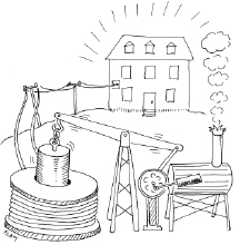
Figure 5-22.
Because inductance increases with the diameter of a coil and with the square of the number of turns, your power output from moving a magnet through the coil can increase dramatically with scale. Those wishing to live “off the grid” may consider this steam-powered configuration, suitable for powering a three-bedroom home.
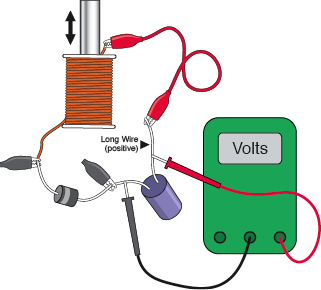
Figure 5-23.
Using a diode in series with a capacitor, you can charge the capacitor with the pulses of current that you generate by moving the magnet through the center of the coil. This demo illustrates the principle of rectifying alternating current.
Experiment 27: Loudspeaker Destruction
I’d like you to sacrifice a 2-inch loudspeaker, even though it means wasting the $5 or so that it probably costs. Actually, I don’t consider this a waste, because if you want to learn how a component works, there’s no substitute for actually seeing inside it. You might also have such a speaker already, part of a piece of cast-off personal electronics or toy you have in your basement.
You will need:
- Cheapest possible 2-inch loudspeaker. Quantity: 1. Figure 5-24 shows a typical example.
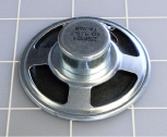
Figure 5-24.
A 2-inch loudspeaker can be instructively destroyed with a utility knife or X-Acto blade.
Procedure
Turn the loudspeaker face-up (as shown in Figure 5-25) and cut around the edge of its cone with a sharp utility knife or X-Acto blade. Then cut around the circular center and remove the ring of black paper that you’ve created. The result should look like Figure 5-26: you should see the flexible neck of the loudspeaker, which is usually made from a yellow weave. If you cut around its edge, you should be able to pull up the hidden paper cylinder, which has the copper coil of the loudspeaker wound around it. In Figure 5-27, I’ve turned it over so that it is easily visible. The two ends of this copper coil normally receive power through two terminals at the back of the speaker. When it sits in the groove visible between the inner magnet and the outer magnet, the coil reacts to voltage fluctuations by exerting an up-and-down force in reaction to the magnetic field. This vibrates the cone of the loudspeaker and creates sound waves.
Large loudspeakers in your stereo system work exactly the same way. They just have bigger magnets and coils that can handle more power (typically, as much as 100 watts).
Whenever I open up a small component like this, I’m impressed by the precision and delicacy of its parts, and the way it can be mass-produced for such a low cost. I imagine how astonished the pioneers of electrical theory (such as Faraday and Henry) would be, if they could see the components that we take for granted today. Henry spent days and weeks winding coils by hand to create electromagnets that were far less efficient than this cheap little loudspeaker.

Figure 5-25.
Loudspeaker ready for creative destruction.

Figure 5-26.
The cone has been removed.

Figure 5-27.
The neck of the cone has been pulled out. Note the coil of copper wire, which fits precisely in the groove between two magnets in the base of the speaker.
Background
Origins of loudspeakers
Loudspeakers utilize the fact that if you run a varying electrical current through a coil situated in a magnetic field, the coil will move in response to the current. This idea was introduced in 1874 by Ernst Siemens, a prolific German inventor. (He also built the world’s first electrically powered elevator in 1880.) Today, Siemens AG is one of the largest electronics companies in the world.
When Alexander Graham Bell patented the telephone in 1876, he used Siemen’s concept to create audible frequencies in the earpiece. From that point on, sound-reproduction devices gradually increased in quality and power, until Chester Rice and Edward Kellogg at General Electric published a paper in 1925 establishing basic principles that are still used in loudspeaker design today.
At
http://www.radiolaguy.com/Showcase/Gallery-HornSpkr.htm
you’ll find photographs of very beautiful early loudspeakers, which used a horn design to maximize efficiency. As sound amplifiers became more powerful, speaker efficiency became less important compared with quality reproduction and low manufacturing costs. Today’s loudspeakers convert only about 1% of electrical energy into acoustical energy.
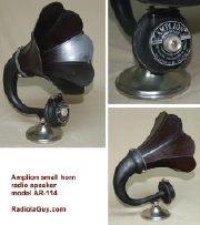
Figure 5-28.
This beautiful Amplion AR-114x illustrates the efforts of early designers to maximize efficiency in an era when the power of audio amplifiers was very limited. Photos by “Sonny, the RadiolaGuy.” Many early speakers are illustrated at www.radiolaguy.com. Some are for sale.
Theory
Sound, electricity, and sound
Time now to establish a clear idea of how sound is transformed into electricity and back into sound again.
Suppose someone bangs a gong with a stick. The flat metal face of the gong vibrates in and out, creating sound waves. A sound wave is a peak of higher air pressure, followed by a trough of lower air pressure.
The wavelength of the sound is the distance (usually ranging from meters to millimeters) between one peak of pressure and the next peak.
The frequency of the sound is the number of waves per second, usually expressed as hertz.
Suppose we put a very sensitive little membrane of thin plastic in the path of the pressure waves. The plastic will flutter in response to the waves, like a leaf fluttering in the wind. Suppose we attach a tiny coil of very thin wire to the back of the membrane so that it moves with the membrane, and let’s position a stationary magnet inside the coil of wire. This configuration is like a tiny, ultra-sensitive loudspeaker, except that instead of electricity producing sound, it is configured so that sound produces electricity. Sound pressure waves make the membrane move to and fro along the axis of the magnet, and the magnetic field creates a fluctuating voltage in the wire.
This is known as a
moving-coil
microphone. There are other ways to build a microphone, but this is the configuration that is easiest to understand. Of course, the voltage that it generates is very small, but we can amplify it using a transistor, or a series of transistors. Then we can feed the output through the coil around the neck of a loudspeaker, and the loudspeaker will recreate the pressure waves in the air. Figures 5-29 through 5-32 illustrate this sequence.
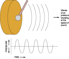
Figure 5-29.
Step 1 in the process of converting sound to electricity, and back again. When the hammer hits the gong, the face of the gong vibrates, creating pressure waves that travel through the air.
