Make: Electronics (60 page)
Authors: Charles Platt

Usually an OR gate has only two logical inputs. Will this prevent me from adding more players? No, because you can actually buy an OR that has eight inputs. If any one of them is high, the output is high. For fewer than eight players, I can short the unused inputs to ground, and ignore them.
Looking again at Figure 4-91, I’m getting a clearer idea of what the thing I’ve called a “button blocker” should actually be. I think it should be another logic gate. It should say, “If there’s only one input, from a button, I’ll let it through. But if there is a second input from the OR gate, I won’t let it through.”
That sounds like a NAND gate, but before I start choosing chips, I have to decide what the latch will be. I can buy an off-the-shelf flip-flop, which flips “on” if it gets one signal and “off” if it gets another, but the trouble is, chips containing flip-flops tend to have more features than I need for a simple circuit like this. Therefore I’m going to use 555 timers again, in flip-flop mode. They require very few connections, work very simply, and can deliver a good amount of current. The only problem with them is that they require a negative input at the trigger pin to create a positive output. But I think I can work with that.
So now, finally, here’s a simplified schematic, in Figure 4-92. I like to show the pins of the 555 timers in their correct positions, so I had to move the components around a little to minimize wire crossovers, but you can see that logically, it’s the same basic idea.
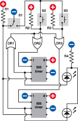
Figure 4-92.
Now that the basic concept of the quiz circuit has been roughed out, specific components can be inserted, with compatible inputs and outputs.
Before you try to build it, just run through the theory of it, because that’s the final step, to make sure there are no mistakes. The important thing to bear in mind is that because the 555 needs a negative input on its trigger pin to create its output, when any of the players presses a button, the button has to create a negative “flow” through the circuit. This is a bit counterintuitive, so I’m including a three-step visualization in Figure 4-93, showing how it will work.
In Step 1, the quizmaster has asked a question and flipped his switch to the right, to supply (negative) power to the players’ buttons. So long as no one presses a button, the pull-up resistors supply positive voltage to OR2 and OR3. An OR gate has a positive output if it has any positive input, so OR2 and OR3 keep the trigger inputs of the 555 timers positive. Their outputs remain low, and nothing is happening yet.
In Step 2, the lefthand player has pressed his button. Now OR2 has two negative inputs, so its output has gone low. But IC1 hasn’t reacted yet.
In Step 3, just a microsecond later, IC1 has sensed the low voltage on its trigger, so its output from pin 3 has gone high, lighting the LED. Remember, this 555 timer is in flip-flop mode, so it locks itself into this state immediately. Meanwhile its high output also feeds back to OR1. Because OR1 is an OR gate, just one high input is enough to make a high output, so it feeds this back to OR2 and OR3. And now that they have high inputs, their outputs also go high, and will stay high, regardless of any future button-presses.
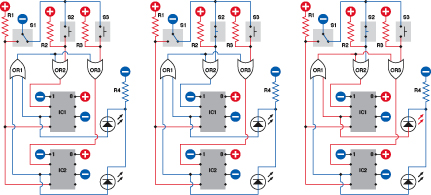
Figure 4-93.
These three schematics show the prevalence of higher and lower voltages (red and blue lines) through the quiz circuit when a pushbutton is pressed.
Because OR2 and OR3 now have high inputs and outputs, IC1 and IC2 cannot be triggered. But IC1 is still locked into its “on” state, keeping the LED illuminated.
The only way to change IC1 is if the quizmaster flips his switch back to the left. That applies negative power to the reset pins of both the timers. Consequently their outputs go low, the LED goes out, and the circuit goes back into the same state as where it started. Having reset it, the quizmaster can ask another question, but the players’ buttons are not activated until the quizmaster flips the switch back to the right again.
There’s only one situation that I haven’t addressed: what if both players press their buttons absolutely simultaneously? In the world of digital electronics, this is highly unlikely. Even a difference of a microsecond should be enough time for the circuit to react and block the second button. But if somehow both buttons are pressed at the same instant, both of the timers should react, and both of the LEDs will light up, showing that there has been a tie.
In case you feel a little uncertain about the way in which a two-player circuit can be upgraded to handle extra players, I’ve included a simplified three-player schematic in Figure 4-94.
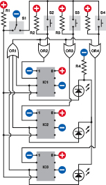
Figure 4-94.
The two-player schematic in can be easily upgraded to a three-player version, as shown here, provided the first OR gate can handle three inputs.
Breadboarding It
Now it’s time to create a schematic that’s as close to the breadboard layout as possible, so that you can build this thing easily. The schematic is shown in Figure 4-95 and the actual components on a breadboard are in Figure 4-96. Because the only logic gates that I’ve used are OR gates, and there are only three of them, I just need one logic chip: the 74HC32, which contains four 2-input OR gates. (I’ve grounded the inputs to the fourth). The two OR gates on the left side of the chip have the same functions as OR2 and OR3 in my simplified schematic, and the OR gate at the bottom-right side of the chip works as OR1, receiving input from pin 3 of each 555 timer. If you have all the components, you should be able to put this together and test it quite quickly.
You may notice that I’ve made one modification of the previous schematic. A 0.01 µF capacitor has been added between pin 2 of each 555 timer (the Input) and negative ground. Why? Because when I tested the circuit without the capacitors, sometimes I found that one or both of the 555 timers would be triggered simply by flipping S1, the quizmaster switch, without anyone pressing a button.
At first this puzzled me. How were the timers getting triggered, without anyone doing anything? Maybe they were responding to “bounce” in the quizmaster switch. Sure enough, the small capacitors solved the problem. They may also slow the response of the 555 timers fractionally, but not enough to interfere with slow human reflexes.
As for the buttons, it doesn’t matter if they “bounce,” because each timer locks itself on at the very first impulse and ignores any hesitations that follow.
You can experiment building the circuit, disconnecting the 0.01 µF capacitors, and flipping S1 to and fro a dozen times. If you have a high-quality switch, you may not experience any problem. If you have a lower-quality switch, you may see a number of “false positives.” I’m going to explain more about “bounce,” and how to get rid of it, in the next experiment.
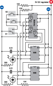
Figure 4-95.
Applying the simplified schematic to a breadboard inevitably entails a wiring layout that is less intuitively obvious and appears more complex. The connections are the same, though.
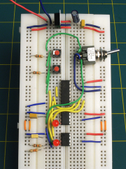
Figure 4-96.
The quiz schematic applied to a breadboard, to test the concept prior to full-scale implementation.
Enhancements
After you breadboard the circuit, if you proceed to build a permanent version, I suggest that you expand it so that at least four players can participate. This will require an OR gate capable of receiving four inputs. The 74HC4078 is the obvious choice, as it allows up to eight. Just connect any unused inputs to negative ground.
Alternatively, if you already have a couple of 74HC32 chips and you don’t want to bother ordering a 74HC4078, you can gang together three of the gates inside a single 74HC32 so that they function like a four-input OR. Look at the simple logic diagram in Figure 4-97 showing three ORs, and remember that the output from each OR will go high if at least one input is high.
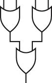
Figure 4-97.
Although a four-input OR gate is not manufactured, its functionality can be achieved easily by linking three 2-input OR gates together.