Windows Server 2008 R2 Unleashed (236 page)
Read Windows Server 2008 R2 Unleashed Online
Authors: Noel Morimoto

1196
CHAPTER 29
System-Level Fault Tolerance (Clustering/Network Load Balancing)
FIGURE 29.3
Defining the network name and IPv4 address for the failover cluster.
7. On the Confirmation page, review the settings, and click Next to create the cluster.
8. On the Summary page, review the results of the cluster creation process, and click
ptg
Finish to return to the Failover Cluster Manager console. If there are any errors, you
can click the View Report button to reveal the detailed cluster creation report.
9. Back in the Failover Cluster Manager console, select the cluster name in the tree
pane, if not already selected by default, and in the tasks pane, review the configura-
tion of the cluster.
10. In the tree pane, select and expand the cluster to reveal the Nodes group to list all of
the cluster nodes.
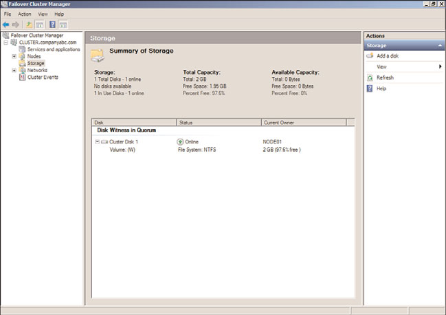
11. Select Storage and review the cluster storage in the tasks pane listed under Storage, as
shown in Figure 29.4.
12. Expand Networks in the tree pane to review the list of networks. Select each network
and review the names of the adapters in each network.
13. When reviewing is completed, the initial cluster deployment is complete. Close the
Failover Cluster Manager console and log off of the cluster node.
After the cluster is created, additional tasks should be performed before any Services and
Applications groups are created using the High Availability Wizard. These tasks can
include, but might not require, customizing the cluster networks, adding storage to the
cluster, adding nodes to the cluster, and changing the cluster quorum model.
Configuring Cluster Networks
After the cluster is created, several steps should be taken to improve cluster management.
One of these tasks includes customizing the cluster networks. Each node in the cluster
should have the same number of network adapters and each adapter should have already
Deploying Failover Clusters
1197
FIGURE 29.4
Displaying the dedicated cluster storage.
ptg
been renamed to describe a network or to easily identify which network a particular
network adapter belongs to. After the nodes are added to the failover cluster, for each
network card in a cluster node, there will be a corresponding cluster network. Each cluster
network will be named “Cluster Network 1,” “Cluster Network 2,” and so forth for each
network. Each network can be renamed and can also be configured for use by the cluster
and clients, for internal cluster use only, or the network can be excluded from any cluster
use. Networks and network adapters used for iSCSI communication must be excluded from
cluster usage. Now excluding iSCSI networks from cluster usage might seem strange, espe-
cially if iSCSI disks are used for the cluster, but this is intended to ensure that only iSCSI
communication is passed to that network and no unnecessary cluster communication is
competing for NIC resources when disk access might be critical. To customize the cluster
networks, perform the following steps:
29
1. Log on to one of the Windows Server 2008 R2 cluster nodes with an account with
administrator privileges over all nodes in the cluster.
2. Click Start, click All Programs, click Administrative Tools, and select Failover
Cluster Manager.
3. When the Failover Cluster Manager console opens, if necessary type in the name of
the local cluster node to connect to the cluster.
4. When the Failover Cluster Manager console connects to the cluster, select and
expand the cluster name.
1198
CHAPTER 29
System-Level Fault Tolerance (Clustering/Network Load Balancing)
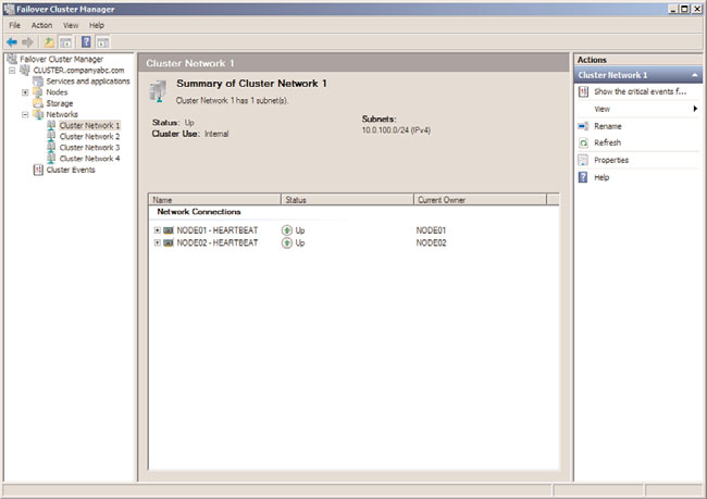
5. Select and expand Networks in the tree pane, and select Cluster Network 1 as an
example.
6. In the tasks pane, review the name of the network adapters in the network, as
shown in Figure 29.5, for the HEARTBEAT network adapters that are members of
Cluster Network 1.
ptg
FIGURE 29.5
Displaying the network adapters in a cluster network.
7. Right-click Cluster Network 1, and select Rename. Rename the cluster to match the
network adapter name.
8. For this example, right-click the renamed HEARTBEAT network, and select
Properties.
9. Select the Allow Cluster Communication on This Network option button, and do
not check the check box to allow clients to connect through this network. Click OK
when completed.
10. Back in the Failover Cluster Manager console, rename the remaining cluster
networks and verify that each network is configured for the proper cluster only or
cluster and client communication. iSCSI network interface cards should be config-
ured to not allow cluster network communication and production networks should
be configured to allow cluster network communication and to allow clients to
connect through the network.
Deploying Failover Clusters
1199
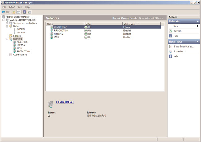
11. When all of the networking changes are complete, click on the Networks node in
the tree pane and the networks should be listed similarly to Figure 29.6. Close the
Failover Cluster Manager console and log off of the server.
ptg
FIGURE 29.6
Cluster networks defined for internal, disabled, and client communication.
Adding Nodes to the Cluster
If additional nodes need to be added to the cluster after the initial cluster creation process,
first join that server to the domain, add the failover clustering feature, configure the
network interface cards and storage configuration per cluster specifications, and then
perform the following steps:
1. Log on to one of the Windows Server 2008 R2 cluster nodes with an account with
administrator privileges over all nodes in the cluster.
29
2. Click Start, click All Programs, click Administrative Tools, and select Failover
Cluster Manager.
3. When the Failover Cluster Manager console opens, if necessary type in the name of
the local cluster node to connect to the cluster.
4. When the Failover Cluster Manager console connects to the cluster, select and
expand the cluster name.
5. Select and expand Nodes in the tree pane.
6. Right-click Nodes and select Add Node.
1200
CHAPTER 29
System-Level Fault Tolerance (Clustering/Network Load Balancing)
7. When the Add Node Wizard opens, click Next on the Before You Begin page.
8. On the Select Server page, type in the name of the cluster node, and click the Add
button. After the node is added to the list, click Next to continue.
9. If this node was not previously included with the original run of the Cluster
Validation Wizard, a Validation Warning page appears. Select the Yes option button
to check this node for cluster validation before adding it to the cluster or select No if
support from Microsoft is not desired or required, and click Next to continue. If you
selected Yes, the validation wizard will open and all nodes will be tested again. Once
completed and validation results are successful, continue with the remaining steps in
this process.
10. On the Confirmation page, review the names of the node or nodes that will be
added, and click Next to continue.
11. When the process completes, review the results on the Summary page, and click
Finish to close the wizard.
12. Close the Failover Cluster Manager console and log off of the server.
Adding Storage to the Cluster
When shared storage is used with failover clusters, all of the LUNs or targets presented to
ptg
the cluster hosts might not have been added to the cluster during the initial configura-
tion. When this is the case, and additional storage needs to be added to the cluster,
perform the following steps:
1. Log on to one of the Windows Server 2008 R2 cluster nodes with an account with
administrator privileges over all nodes in the cluster.
2. Click Start, click All Programs, click Administrative Tools, and select Failover
Cluster Manager.
3. When the Failover Cluster Manager console opens, if necessary type in the name of
the local cluster node to connect to the cluster.
4. In the tree pane, expand the desired cluster Services and Applications group, select
Storage, right-click Storage, and select Add a Disk.
5. If suitable storage is ready to be added to the cluster, it will be listed in the Add Disks
to a Cluster window. If a disk is listed, check the box next to the desired disk or
disks, and click OK to add the disk(s) to the cluster. The disks will need to be basic
disks and set to online in Disk Manager on one of the cluster nodes and should
already have a single partition and drive letter. It is essential that drive letters used
for cluster disks are not in conflict with any drive letters on any node in the cluster,
including optical or external drives.
6. After the process completes, if necessary change the drive letter of the new disk.
Once this process completes, if Disk Manager is opened on the cluster nodes, disks
will show as Basic and Reserved on all cluster nodes, but only the active cluster node
will show the disk partition and drive letter information.
7. Close the Failover Cluster Manager console.
Deploying Failover Clusters
1201
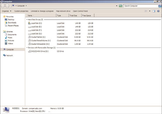
8. Click the Start button and select Computer.
9. Review the list of disks on the cluster node and note that disks managed by the
cluster are listed as Clustered Disks instead of Local Disks, as shown in Figure 29.7.
ptg
FIGURE 29.7
Displaying the local and clustered disks on a cluster node.