Make: Electronics (42 page)
Authors: Charles Platt

D1 is a red LED, D2 is a green LED, J1 is a power input jack (to be connected with an external 12-volt supply), and R1 is a 680Ω resistor to protect the LEDs. Note that J1 follows the usual practice of supplying positive voltage in its center contact, and negative in the circular shell around the center.
When S1 is in its Off position, it still supplies positive power through its upper contact to S2, the pushbutton. When the pushbutton is pressed, so that it goes into its “Test” position, the pole of S2 connects with the power and sends it out through the sensor switches on doors and windows. The wires to these switches will be attached via a couple of binding posts, shown here as two circles. If the sensor switches are all closed, power returns through the second binding post, passes through the lower set of contacts in S2, and lights D2, the green LED. Because S1 is not supplying power to the alarm circuit board, the alarm does not sound at this time.
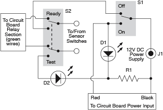
Figure 3-106.
This schematic suggests a convenient way to add an on/off switch, a continuity testing feature, and a noisemaker testing feature to the alarm.
Now if S1 is turned to its On position, it sends power to the components on the perforated board. The relay section of the circuit sends power out along the green wires to S2, and as long as the button is not being pressed, the power goes out through the switch network and back through S2, to the relay section, just as before S2 was spliced in. So the alarm remains silent. But as soon as a sensor switch is opened, the circuit is broken and the alarm sounds. The only way to stop it will be by switching S1 into its Off position.
Finally, if you press S2, the pushbutton, while S1 is in its On mode, you interrupt the network of switches and activate the noisemaker. In this way, S2 does dual duty: when S1 is off, pushbutton S2 tests the sensor switches for continuity. When S1 is on, S2 tests the noisemaker to make sure it creates a noise. I think this is the simplest possible way to implement these features.
Installing the Switches
If you bought a project box from RadioShack, it may have come with two optional top panels: one made of metal, the other made of plastic. I’ll assume that you’ll use the plastic one, as you’ll have more trouble drilling holes in metal. The type of plastic used by RadioShack is ABS, which is very easy to shape with the tools that I have recommended.
You have to choose a layout for the switches and other components that will share the top panel of the project box. I like a layout to be neat, so I take the trouble to draw it using illustration software, but a full-size pencil sketch is almost as good. Just make sure there’s room for the components to fit together, and try to place them similarly to the schematic, to minimize the risk of confusion.
Tape your sketch to the inside of the top panel, as shown in Figure 3-107, and then use a sharp pointed tool, such as a pick, to press through and mark the plastic at the center of each hole. The indentations will help to center your bit when you drill the holes. Remember that you’ll need to make multiple holes to vent the sound from the loudspeaker, which will be beneath the top panel of the box. The result is shown in Figure 3-108.
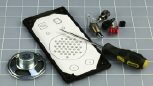
Figure 3-107.
A printed layout for the switches, LEDs, and other components has been taped to the underside of the lid of the project box. An awl is pressed through the paper to mark the center of each hole to be drilled in the lid.
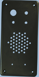
Figure 3-108.
The exterior of the panel after drilling. A small handheld cordless drill can create a neat result if the holes were marked carefully.
I placed all the components on the top panel, with the exception of the power input jack, which I positioned at one end of the box. Naturally, each hole has to be sized to fit its component, and if you have calipers, they’ll be very useful for taking measurements and selecting the right drill bit. Otherwise, make your best guess, too small being better than too large. A deburring tool is ideal for slightly enlarging a hole so that a component fits snugly. This may be necessary if you drill 3/16-inch holes for your 5-inch mm LEDs. Fractionally enlarge each hole, and the LEDs should push in very snugly.
If your loudspeaker lacks mounting holes, you’ll have to glue it in place. I used five-minute epoxy to do this. Be careful not to use too much. You don’t want any of the glue to touch the speaker cone.
Drilling large holes in the thin, soft plastic of a project box can be a problem. The drill bit tends to dig in and create a mess. You can approach this problem in one of three ways:
1.
Use a Forstner drill bit if you have one. It creates a very clean hole.
2.
Drill a series of holes of increasing size.
3.
Drill a smaller hole than you need, and enlarge it with a deburring tool.
Regardless of which approach you use, you’ll need to clamp or hold the top panel of the project box with its outside surface face-down on a piece of scrap wood. Then drill from the inside, so that your bit will pass through the plastic and into the wood.
Finally, mount the components in the panel, as shown in Figure 3-109, and turn your attention to the underneath part of the box.
The circuit board will sit on the bottom, held in place with four #4-size machine screws (bolts) with washers and nylon-insert locknuts. You need to use locknuts to eliminate the risk of a nut working loose and falling among components where it can cause a short circuit.
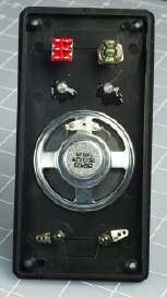
Figure 3-109.
Components have been added to the control panel of the project box (seen from the underside). The loudspeaker has been glued in place. Spare glue was dabbed onto the LEDs, just in case. The SPDT on/off switch is at the top right, the DPDT pushbutton is at top left, and the binding posts, which will connect with the network of magnetic sensor switches, are at the bottom.
You’ll have to cut the perfboard to fit, taking care not to damage any of the components on it. Also check the underside the board for loose fragments of copper traces after you finish cutting.
Drill bolt holes in the board, if necessary, taking care again not to damage any components. Then mark through the holes to the plastic bottom of the box, and drill the box. Countersink the holes (i.e., bevel the edges of a hole so that a flat-headed screw will fit into it flush with the surrounding surface), push the little bolts up from underneath, and install the circuit board. Be extremely careful not to attach the circuit board too tightly to the project box. This can impose bending stresses, which may break a joint or a copper trace on the board.
I like to include a soft piece of plastic under the board to absorb any stresses. Because you’re using locknuts, which will not loosen, there’s no need to make them especially tight.
Test the circuit again after mounting the circuit board, just in case.
Soldering the Switches
Figure 3-110 shows how the physical switches should be wired together. Remember that S1 is a toggle switch and S2 is a DPDT pushbutton. Your first step is to decide which way up they should be. Use your meter to find out which terminals are connected when the switch is flipped, and when the button is pressed. You’ll probably want the switch to be on when the toggle is flipped upward. Be especially careful with the orientation of the pushbutton, because if you wire it upside-down, it will constantly have the alarm in “test” mode, which is not what you want.
Remember, the center terminal of any double-throw switch is almost always the pole of the switch, connecting with the terminals immediately above it and below it.
Stranded wire is appropriate to connect the circuit board with the components in the top panel, because the strands flex easily and impose less stress on solder joints. Twisting each pair of wires together helps to minimize the mess.
Remember to install the LEDs with their short, negative wires connected with the resistor. This will entail some wire-to-wire soldering. You may want to protect some of these bare leads and joints with thin heat-shrink tubing, to minimize the risk of short circuits when you push all the parts into the box.
When you connect wires or components with the lugs on the switches, your pencil-style soldering iron probably won’t deliver enough heat to make good joints. You can use your higher-powered soldering iron in these locations, but you absolutely must apply a good heat sink to protect the LEDs when you attach them, and don’t allow the iron to remain in contact with anything for more than 10 seconds. It will quickly melt insulation, and may even damage the internal parts of the switches.
In projects that are more complex than this one, it would be good practice to link the top panel with the circuit board more neatly. Multicolored ribbon cable is ideal for this purpose, with plug-and-socket connectors that attach to the board. For this introductory project, I didn’t bother. The wires just straggle around, as shown in Figure 3-111.
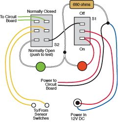
Figure 3-110.
The components can be wired together like this to replicate the circuit shown in The red and green circles are LEDs. Small, solid black circles indicate wire-to-wire solder joints.
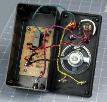
Figure 3-111.
The circuit board has been installed in the base of the project box, and the power input jack has been screwed into the end of the box. Twisted wire-pairs have been connected on a point-to-point basis, without much concern over neatness, as this is a relatively small project. The white insulation at the top-right corner of the front panel is heat-shrink tube that encloses a solder joint and the 680Ω load resistor. Soldering wires to the pushbutton switch requires care and precision, as the contacts are closely spaced.