Make: Electronics (44 page)
Authors: Charles Platt

IC sockets
I suggest that you avoid soldering chips directly onto perforated board. If you damage them, they’re difficult to remove. Buy some DIP sockets, solder the sockets onto the board, and then plug the chips into the sockets. You can use the cheapest sockets you can find (you don’t need gold-plated contacts for our purposes). You will need 8-pin, 14-pin, and 16-pin DIP sockets, such as parts 276-1995, 276-1999, and 276-1998 from RadioShack. See Figure 4-5. Quantity of each: 5 minimum.
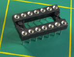
Figure 4-5.
When you’re soldering a circuit onto perforated board, sockets eliminate the risk of overheating integrated circuit chips and reduce the risk of zapping them with static electricity, and enable easy replacement.
Low-power LEDs
The logic chips that you’ll be using are not designed to deliver significant power. You’ll need to add transistors to amplify their output if you want to drive bright LEDs or relays. Because adding transistors is a hassle, I suggest an alternative: Special low-power LEDs that will draw as little as 1mA, such as the Everlight model T-100 Low Current Red, part number HLMPK150. Figure 4-6 shows a size comparison with a regular 5mm LED. Quantity: 10 (at a minimum).
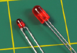
Figure 4-6.
An HC series logic chip is rated to deliver only 4mA at each pin. This is inadequate to drive a typical 5 mm LED (right), which is rated for 20mA forward current. Miniature, low-current LEDs (left) will use as little as 1mA in series with a suitable resistor, and are ideal for test circuits in which you want to see the output with a minimum of hassle.
LED numeric displays
In at least one of our projects, you’ll want to illuminate some seven-segment LED numerals. You’ll need either three individual numerals, or one package containing three numerals, such as the Kingbright High Efficiency Red Diffused, part number BC56-11EWA, which will be specifically referred to in schematics in this book. If you buy a different seven-segment display, it must be an LED with a “common cathode.” (Don’t buy liquid-crystal LCD numerals; they require different electronics to drive them.) If you have a choice of power consumption, buy whichever product consumes the least current. See Figure 4-7.
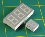
Figure 4-7.
Seven-segment displays are the simplest way to show a numeric output and can be driven directly by some CMOS chips. For finished projects, they are typically mounted behind transparent red acrylic plastic panels.
Latching relays
You’re going to need a 5-volt latching relay that has two coils, instead of one. The first coil flips the relay one way; the second coil flips it back. The relay consumes no additional power while remaining passively in each state. I suggest the Panasonic DS2E-SL2-DC5V relay. If you buy a different relay, it must be dual-coil latching to run off 5 volts DC, switching at least 1 amp, in a “2 form C” package, to fit your breadboard.
Potentiometers
You’ll need 5K, 10K, and 100K linear potentiometers (one of each). Also, a 10K trimmer potentiometer (which you may find described just as a “trimmer”). The manufacturer is unimportant.
Voltage regulators
Because many logic chips require precisely 5 volts DC, you need a voltage regulator to deliver this. The LM7805 does the job. Here again, the chip number will be preceded or followed with an abbreviation identifying the manufacturer and package style, as in the LM7805CT from Fairchild. Any manufacturer will do, but the package should look like the one in Figure 4-8, and if you have a choice, buy a regulator that can deliver at least 1 amp.
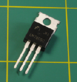
Figure 4-8.
Many integrated circuit chips require a controlled power supply of 5 volts, which can be delivered by this regulator when you apply 7.5 to 9 volts to it. The lefthand pin is for positive input, the center pin is a common ground, and the righthand pin is the 5V output. For currents exceeding 250mA, you should bolt the regulator to a metal heat sink using the hole at the top.
Tactile switches
These are SPST pushbuttons (momentary switches), usually with four legs. Look for the ALPS part number SKHHAKA010 or any similar item that has pins to fit your breadboard or perforated board. See Figure 4-9.
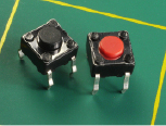
Figure 4-9.
A tactile switch delivers tactile feedback through your fingertip when you press it. They are almost always SPST pushbuttons designed for mounting in circuit boards with standard 1/10-inch hole spacing.
12-key numeric keypad
Velleman “12 keys keyboard with common output” (no part number, but has been available through All Electronics under catalog code KP-12). Quantity: 1.
This type of keypad has the same layout as an old-fashioned touchtone phone. It should have at least 13 pins or contacts, 12 of which connect with individual pushbuttons, the thirteenth connecting with the other side of all the pushbuttons. In other words, the last pin is “common” to all of them, and this type of keypad is often described as having a “common output.” The type of keypad that you don’t want is “matrix-encoded,” with fewer than 13 contacts, requiring additional external circuitry. See Figures 4-10 and 4-11. If you can’t find the Velleman keypad that I suggest, look carefully at keypad descriptions and photographs to make sure that the one you buy is not matrix-encoded and has a common terminal.
Alternatively, you may substitute 12 cheap SPST NO pushbuttons and mount them in a small project box.
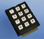
Figure 4-10.
When shopping for a numeric keypad, it should have 12 keys in “touchtone phone” layout, and should have at least 13 contacts for input/output. The contacts are visible here along the front edge.
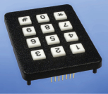
Figure 4-11.
This keypad has insufficient pins and will not work in the circuit in this book.
Background
How chips came to be
The concept of integrating solid-state components into one little package originated with British radar scientist Geoffrey W. A. Dummer, who talked about it for years before he attempted, unsuccessfully, to build one in 1956. The first true integrated circuit wasn’t fabricated until 1958 by Jack Kilby, working at Texas Instruments. Kilby’s version used germanium, as this element was already in use as a semiconductor. (You’ll encounter a germanium diode when I deal with crystal radios in the next chapter of this book.) But Robert Noyce, pictured in Figure 4-12, had a better idea.
Born in 1927 in Iowa, in the 1950s Noyce moved to California, where he found a job working for William Shockley. This was shortly after Shockley had set up a business based around the transistor, which he had coinvented at Bell Labs.
Noyce was one of eight employees who became frustrated with Shockley’s management and left to establish Fairchild Semiconductor. While he was the general manager of Fairchild, Noyce invented a silicon-based integrated circuit that avoided the manufacturing problems associated with germanium. He is generally credited as the man who made integrated circuits possible.
Early applications were for military use, as Minuteman missiles required small, light components in their guidance systems. These applications consumed almost all chips produced from 1960 through 1963, during which time the unit price fell from around $1,000 to $25 each, in 1963 dollars.
In the late 1960s, medium-scale integration chips emerged, each containing hundreds of transistors. Large-scale integration enabled tens of thousands of transistors on one chip by the mid-1970s, and today’s chips can contain as many as several billion transistors.
Robert Noyce eventually cofounded Intel with Gordon Moore, but died unexpectedly of a heart attack in 1990. You can learn more about the fascinating early history of chip design and fabrication at
http://
www.siliconvalley
historical.org
.

Figure 4-12.
This picture of Robert Noyce, late in his career, is from the Wikimedia Commons.
