Make: Electronics (45 page)
Authors: Charles Platt

Experiment 16: Emitting a Pulse
I’m going to introduce you to the most successful chip ever made: the 555 timer. As you can find numerous guides to it online, you might question the need to discuss it here, but I have three reasons for doing so:
1.
It’s unavoidable. You simply have to know about this chip. Some sources estimate that more than 1 billion are still being manufactured annually. It will be used in one way or another in most of the remaining circuits in this book.
2.
It provides a perfect introduction to integrated circuits, because it’s robust, versatile, and illustrates two functions that we’ll be dealing with later: comparators and a flip-flop.
3.
After reading all the guides to the 555 that I could find, beginning with the original Fairchild Semiconductor data sheet and making my way through various hobby texts, I concluded that its inner workings are seldom explained very clearly. I want to give you a graphic understanding of what’s happening inside it, because if you don’t have this, you won’t be in a good position to use the chip creatively.
You will need:
- 9-volt power supply.
- Breadboard, jumper wires, and multimeter.
- 5K linear potentiometer. Quantity: 1.
- 555 timer chip. Quantity: 1.
- Assorted resistors and capacitors.
- SPST tactile switches. Quantity: 2.
- LED (any type). Quantity: 1.
Procedure
The 555 chip is very robust, but still, in theory, you can zap it with a jolt of static electricity and kill it. Therefore, to be on the safe side, you should ground yourself before handling it. See the “Grounding yourself” warning on
page 172
for details. Although this warning primarily refers to the type of chips known as CMOS, which are especially vulnerable, grounding yourself is always a sensible precaution.
Look for a small circular indentation, called the
dimple
, molded into the body of the chip, and turn the chip so that the indentation is at the top-left corner with the pins pointing down. Alternatively, if your chip is of the type with a notch at one end, turn the chip so that the notch is at the top.
The pins on chips are always numbered counterclockwise, starting from the top-left pin (next to the dimple). See Figure 4-13, which also shows the names of the pins on the 555 timer, although you don’t need to know most of them just yet.
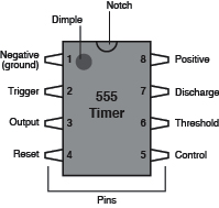
Figure 4-13.
The 555 timer chip, seen from above. Pins on chips are always numbered counterclockwise, from the top-left corner, with a notch in the body of the chip uppermost, or a circular indentation at top-left, to remind you which end is up.
Insert the chip in your breadboard so that its pins straddle the channel down the center. Now you can easily feed voltages to the pins on either side, and read signals out of them. See Figure 4-14 for a precise guide to placement, in the first project. The timer is identified as “IC1,” because “IC” is the customary abbreviation for “Integrated Circuit.”
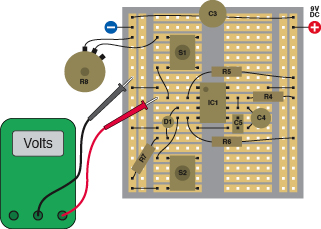
Figure 4-14.
This circuit allows you to explore the behavior of the 555 timer chip. Use your meter to monitor the voltage on pin 2 as shown. There are no resistors labeled R1, R2, or R3 and no capacitors labeled C1 or C2, because they’ll be added in a later schematic. Component values in this schematic:
R4: 100K
R5: 2K2
R6: 10K
R7: 1K
R8: 5K linear potentiometer
C3: 100 µF electrolytic
C4: 47 µF electrolytic
C5: 0.1 µF ceramic
IC1: 555 timer
S1, S2: SPST tactile switches (pushbuttons)
D1: Generic LED
R5 holds the trigger (pin 2) positive until S1 is pressed, which lowers the voltage depending on the setting of potentiometer R8. When the trigger voltage falls below 1/3 of the power supply, the chip’s output (pin 3) goes high for a period determined by the values of R4 and C4. S2 resets (zeros) the timer, by reducing the voltage to pin 4, the Reset. C3 smoothes the power supply, and C5 isolates pin 5, the control, so that it won’t interfere with the functioning of this test circuit. (We’ll use the control pin in a future experiment.)
All integrated circuit chips require a power supply. The 555 is powered with negative voltage applied to pin 1 and positive to pin 8. If you reverse the voltage accidentally, this can permanently damage the chip, so place your jumper wires carefully.
Set your power supply to deliver 9 volts. It will be convenient for this experiment if you supply positive down the righthand side and negative down the lefthand side of the breadboard, as suggested in Figure 4-14. C3 is a large capacitor, at least 100 µF, which is placed across the power supply to smooth it out and provide a local store of charge to fuel fast-switching circuits, as well as to guard against other transient dips in voltage. Although the 555 isn’t especially fast-switching, other chips are, and you should get into the habit of protecting them.
Begin with the potentiometer turned all the way counterclockwise to maximize the resistance between the two terminals that we’re using, and when you apply the probe from your meter to pin 2, you should measure about 6 volts when you press S1.
Now rotate the potentiometer clockwise and press S1 again. If the LED doesn’t light up, keep turning the potentiometer and pressing and releasing the button. When you’ve turned the potentiometer about two-thirds of the way, you should see the LED light up for just over 5 seconds when you press and release the button. Here are some facts that you should check for yourself:
- The LED will keep glowing after you release the button.
- You can press the button for any length of time (less than the timer’s cycle time) and the LED always emits the same length of pulse.
- The timer is triggered by a fall in voltage on pin 2. You can verify this with your meter.
- The LED is either fully on or fully off. You can’t see a faint glow when it’s off, and the transition from off to on and on to off is very clean and precise.
Check Figure 4-16 to see how the components should look on your breadboard, and then look at the schematic in Figure 4-15 to understand what’s happening. I will be adding more components later, which I will be labeling R1, R2, C1, and C2 to be consistent with data sheets that you may see for the 555 timer. Therefore, in this initial circuit the resistors are labeled R4 and up, and capacitors C3 and up.
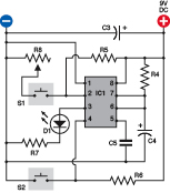
Figure 4-15.
A schematic view of the circuit shown in Figure 4-14. Throughout this chapter, the schematics will be laid out to emulate the most likely placement of components on a breadboard. This is not always the simplest layout, but will be easiest for you to build. Refer to Figure 4-14 for the values of the components.
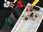
Figure 4-16.
This is how the components look when installed on the breadboard. The alligator clips are attached to a patch cord that links the 100 µF capacitor to the potentiometer. The power supply input is not shown.
When S1 (the tactile switch) is open, pin 2 of the 555 timer receives positive power through R5, which is 2K2. Because the input resistance of the timer is very high, the voltage on pin 2 is almost the full 9 volts.
When you press the button, it connects negative voltage through R8, the 5K potentiometer to pin 2. Thus, R8 and R5 form a voltage divider with pin 2 in the middle. You may remember this concept from when you were testing transistors. The voltage between the resistances will change, depending on the values of the resistances.
If R8 is turned up about halfway, it is approximately equal to R5, so the midpoint, connected to pin 2, has about half the 9-volt power supply. But when you turn the potentiometer so that its resistance falls farther, the negative voltage outweighs the positive voltage, so the voltage on pin 2 gradually drops.
If you have clips on your meter leads, you can hook them onto the nearest jumper wires and then watch the meter while you turn the potentiometer up and down and press the button.
The graphs in Figure 4-17 illustrate what is happening. The upper graph shows the voltage applied to pin 2 by random button-presses, with the potentiometer turned to various values. The lower graph shows that the 555 is triggered if, and only if, the voltage on pin 2 actively drops from above 3 volts to below 3 volts. What’s so special about 3 volts? It’s one-third of our 9-volt power supply.
Here’s the take-home message:
- The output of the 555 (pin 3) emits a
positive
pulse when the trigger (pin 2) drops
below
one-third of the supply voltage. - The 555 delivers the
same duration
of positive pulse every time (so long as you don’t supply a prolonged low voltage on pin 2). - A
larger
value for R4 or for C4 will
lengthen
the pulse. - When the output (pin 3) is high, the voltage is almost equal to the supply voltage. When the output goes low, it’s almost zero.
The 555 converts the imperfect world around it into a precise and dependable output. It doesn’t switch on and off absolutely instantly, but is fast enough to
appear
instant.
Now here’s another thing to try. Trigger the timer so that the LED lights up. While it is illuminated, press S2, the second button, which grounds pin 4, the reset. The LED should go out immediately.
When the reset voltage is pulled
low
, the output goes
low
, regardless of what voltage you apply to the trigger.
There’s one other thing I want you to notice before we start using the timer for more interesting purposes. I included R5 and R6 so that when you first switch on the timer, it is not emitting a pulse—but is ready to do so. These resistors apply a positive voltage to the trigger and the reset pin, to make sure that the 555 timer is ready to run when you first apply power to it.