Make: Electronics (37 page)
Authors: Charles Platt

Finally, the bottom version of the perfboard diagram shows the perfboard flipped left-to-right (notice the L and the R have been transposed to remind you, and I’ve used a darker color to indicate the underside of the board). Orange circles indicate where solder joints will be needed.
The LED should be unpluggable, because we may want to run it at some distance from the circuit. Likewise the power source should be unpluggable. Fortunately we can buy miniature connectors that fit right into the perforated board. You may have to go to large online retail suppliers such as Mouser.com for these. Some manufacturers call them “single inline sockets and headers,” while others call them “boardmount sockets and pinstrip headers.” Refer back to Figure 3-29 and check the shopping list for more details.
This is a very compact design that will require careful work with your pencil-style soldering iron. Because a piece of perforated board as small as this will tend to skitter around, I suggest that you apply your miniature vise to one end to anchor it with some weight while still allowing you to turn it easily.
When I’m working on this kind of project, I like to place it (with the vise attached) on a soft piece of polyurethane foam—the kind of slab that is normally used to make a chair cushion. The foam protects the components from damage when the board is upside-down, and again helps to prevent the work from sliding around unpredictably.
Step by Step
Here’s the specific procedure for building this circuit:
1.
Cut the small piece of perfboard out of a sheet that has no copper traces on it. You can cut the section using your miniature hobby saw, or you may be able to snap the board along its lines of holes, if you’re careful. Alternatively, use a small ready-cut piece of perfboard with copper circles on it that are not connected to one another. You’ll ignore the copper circles in this project. (In the next experiment, you’ll deal with the additional challenge of making connections between components and copper traces on perforated board.)
2.
Gather all the components and carefully insert them through holes in the board, counting the holes to make sure everything is in the right place. Flip the board over and bend the wires from the components to anchor them to the board and create connections as shown. If any of the wires isn’t long enough, you’ll have to supplement it with an extra piece of 22-gauge wire from your supply. You can remove all the insulation, as we’ll be mounting the perfboard on a piece of insulating plastic.
3.
Trim the wires approximately with your wire cutters.
4.
Make the joints with your pencil soldering iron. Note that in this circuit, you are just joining wires to each other. The components are so close together that they’ll prevent each other from wiggling around too much. If you are using board with copper pads (as I did), and some solder connects with them, that’s OK—as long as it doesn’t creep across to the neighboring component and create a short circuit.
5.
Check each joint using a close-up magnifying glass, and wiggle it with pointed-nosed pliers. If there isn’t enough solder for a really secure joint, reheat it and add more. If solder has created a connection that shouldn’t be there, use a utility knife to make two parallel cuts in the solder, and scrape away the little section between them.
Generally, I insert three or four components, trim the wires approximately, solder them, trim their wires finally, then pause to check the joints and the placement. If I solder too many components in succession, there’s a greater risk of missing a bad joint, and if I make an error in placing a component, undoing it will be much more problematic if I have already added a whole lot more components around it.
Figures 3-80 and 3-81 show the version of this project that I constructed, before I trimmed the board to the minimum size.
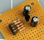
Figure 3-80.
Components mounted on a piece of perforated board.
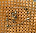
Figure 3-81.
The assembly seen from below. The copper circles around the holes are not necessary for this project. Some of them have picked up some solder, but this is irrelevant as long as no unintentional short circuits are created.
 Flying Wire Segments
The jaws of your wire cutters exert a powerful force that peaks and then is suddenly released when they cut through wire. This force can be translated into sudden motion of the snipped wire segment. Some wires are relatively soft, and don’t pose a risk, but harder wires can fly in unpredictable directions at high speed, and may hit you in the eye. The leads of transistors are especially hazardous in this respect.
I think it’s a good idea to wear safety glasses when trimming wires.
Finishing the Job
I always use bright illumination. This is not a luxury; it is a necessity. Buy a cheap desk lamp if you don’t already have one. I use a daylight-spectrum fluorescent desk lamp, because it helps me identify the colored bands on resistors more reliably. Note that this type of fluorescent lamp emits quite a lot of ultraviolet light, which is not good for the lens in your eye. Avoid looking closely and directly at the tube in the lamp, and if you wear glasses, they will provide additional protection.
No matter how good your close-up vision is, you need to examine each joint with that close-up magnifier. You’ll be surprised how imperfect some of them are. Hold the magnifier as close as possible to your eye, then pick up the thing that you want to examine and bring it closer until it comes into focus.
Finally, you should end up with a working circuit. You can insert the wires from your power supply into two of the tiny power sockets, and plug a red LED into the remaining two sockets. Remember that the two center sockets are negative, and the two outer sockets are positive, because it was easier to wire the circuit this way. You should color-code them to avoid mistakes.
So now you have a tiny circuit that pulses like a heartbeat. Or does it? If you have difficulty making it work, retrace every connection and compare it with the schematic. If you don’t find an error, apply power to the circuit, attach the black lead from your meter to the negative side, and then go around the circuit with the red lead, checking the presence of voltage. Every part of this circuit should show at least some voltage while it’s working. If you find a dead connection, you may have made a bad solder joint, or missed one entirely.
When you’re done, now what? Well, now you can stop being an electronics hobbyist and become a crafts hobbyist. You can try to figure out a way to make this thing wearable.
First you have to consider the power supply. Because of the components that I used, we really need 9 volts to make this work well. How are you going to make this 9-volt circuit wearable, with a bulky 9-volt battery?
I can think of three answers:
1.
You can put the battery in a pocket, and mount the flasher on the outside of the pocket, with a thin wire penetrating the fabric. Note that the tiny power connector on the perforated board will accept two 22-gauge wires if they are solid core, or if they are stranded (like the wires from a 9-volt battery connector) but have been thinly coated with solder.
2.
You could mount the battery inside the crown of a baseball cap, with the flasher on the front.
3.
You can put together three 3-volt button batteries in a stack, held in some kind of plastic clip. If you try this option, it may not be a good idea to try to solder wire to a battery. You will heat the liquid stuff inside the battery, which may not be good for it, and may not be good for you if the liquid starts boiling and the battery bursts open. Also, solder doesn’t stick easily to the metallic finish on most battery terminals.
Most LEDs create a sharply defined beam of light, which you may want to diffuse to make it look nicer. One way to do this is to use a piece of transparent acrylic plastic, at least 1/4 inch thick, as shown in Figure 3-82. Sandpaper the front of the acrylic, ideally using an orbital sander that won’t make an obvious pattern. Sanding will make the acrylic translucent rather than transparent.
Drill a hole slightly larger than the LED in the back of the acrylic. Don’t drill all the way through the plastic. Remove all fragments and dust from the hole by blasting some compressed air into it, or by washing it if you don’t have an air compressor. After the cavity is completely dry, get some transparent silicone caulking or mix some clear five-minute epoxy and put a drop in the bottom of the hole. Then insert the LED, pushing it in so that it forces the epoxy to ooze around it, making a tight seal. See Figure 3-82.
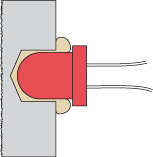
Figure 3-82.
This cross-sectional view shows a sheet of transparent acrylic in which a hole has been drilled part of the way from the back toward the front. Because a drill bit creates a hole with a conical shape at the bottom, and because the LED has rounded contours, transparent epoxy or silicone caulking can be injected into the hole before mounting the LED.
Try illuminating the LED, and sand the acrylic some more if necessary. Finally, you can decide whether to mount the circuit on the back of the acrylic, or whether you want to run a wire to it elsewhere.
Because the LED will flash at about the speed of a human heart while the person is resting, it may look as if it’s measuring your pulse, especially if you mount it on the center of your chest or in a strap around your wrist. If you enjoy hoaxing people, you can suggest that you’re in such amazingly good shape, your pulse rate remains constant even when you’re taking strenuous exercises.
To make a good-looking enclosure for the circuit, I can think of options ranging from embedding the whole thing in clear epoxy to finding a Victorian-style locket. I’ll leave you to consider alternatives, because this is a book about electronics rather than handicrafts.