Make: Electronics (14 page)
Authors: Charles Platt

Components
Pushbutton
Momentary-on, SPST, sometimes referred to as OFF-(ON) or (ON)-OFF type. Must be PCB- or PC-mount, meaning is extremely small with thin spiky contacts on the bottom. Quantity: 1. See Figure 2-11.
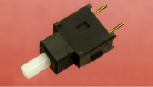
Figure 2-11.
The terminals protruding from this tiny pushbutton are spaced 0.2 inches apart, making it ideal for the “breadboard” that you’ll be using.
Examples are part number AB11AP by NKK, part MPA103B04 by Alcoswitch, or part EP11SD1CBE by C&K. If you have a choice, buy the cheapest, as we’re going to switch very low current.
Switches
Toggle switch, single-pole, double-throw (SPDT), sometimes referred to as ON-ON type. Quantity: 2. See Figure 2-12.
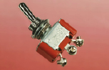
Figure 2-12.
This relatively large toggle switch made by NKK has screw terminals, which will reduce the inconvenience of attaching it to hookup wire.
Model S302T-RO by NKK is ideal; it has screw terminals that will eliminate the need for alligator clips. Other options are catalog item MTS-4PC from All Electronics or part 275-603 from RadioShack.
We won’t be switching large currents or high voltages, so the exact type of switch is unimportant. However, the terminals on larger-size switches are spaced wider apart, which makes them easier to deal with.
Relays
DPDT, nonlatching, 12v DC. Quantity: 2.
It’s important to get the right kind of relay—one whose configuration matches the pictures I’ll be using. Look for parts FTR-F1CA012V or FTR-F1CD012V by Fujitsu, G2RL-24-DC12 by Omron, or OMI-SH-212D by Tyco. Avoid substitutions.
Potentiometer
1 megohm linear potentiometer, Part number 271-211 from RadioShack, part number 24N-1M-15R-R from Jameco, or similar.
Transistors
NPN transistor, general-purpose, such as 2N2222 by STMicroelectronics, part PN2222 by Fairchild, or part 2N2222 from RadioShack. Quantity: 4. See Figure 2-13.
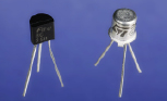
Figure 2-13.
Transistors are commonly sold either in little metal cans or sealed into little lumps of plastic. For our purposes, the packaging makes no difference.
2N6027 programmable unijunction transistor manufactured by On Semiconductor or Motorola. Quantity: 4 (allowing for 2 spares in case of damage).
Capacitors
Electrolytic capacitors, assorted. Must be rated for a minimum of 25 volts and include at least one capacitor of 1,000 μF (microfarads) and two capacitors of 2.2 μF. If you search on eBay, make sure you find
electrolytic
capacitors. If they’re rated for higher voltages, that’s OK, although they will be physically larger than you need. See Figure 2-14.
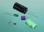
Figure 2-14.
An assortment of electrolytic capacitors.
Ceramic capacitors, assorted. Make sure you get at least one rated at 0.0047 μF (which can also be written as 4.7 nF). See Figure 2-15.
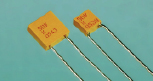
Figure 2-15.
Ceramic capacitors mostly look like this, although many of them are round or bead-shaped instead of square. The packaging shape is unimportant to us.
Resistors
If you bought only a minimal selection for experiments 1 through 5, now’s the time to buy a larger assortment, so that you won’t be stuck needing the one value that you don’t have. 1/4-watt minimum.
Loudspeaker
Any 8Ω, 1-inch miniature loudspeaker such as part 273-092 from RadioShack. See Figure 2-16.
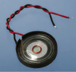
Figure 2-16.
This miniature loudspeaker, just over 1 inch in diameter, is useful for verifying audio output direct from transistor circuits.
Experiment 6: Very Simple Switching
You will need:
- AA batteries. Quantity: 2.
- Battery carrier for 2 AA batteries. Quantity: 1.
- LED. Quantity: 1.
- Toggle switches, SPDT. Quantity: 2. See Figure 2-12.
- 220Ω or similar value resistor, 1/4-watt minimum. Quantity: 1.
- Alligator clips. Quantity: 8.
- Wire or patch cords. See Figure 2-10, shown previously.
- Wire cutters and wire strippers if you don’t use patch cords. See Figure 2-4, shown previously.
In
Experiment 3
, you illuminated an LED by attaching a battery, and switched it off by removing the battery. For greater convenience our circuits should have proper switches to control power, and while I’m dealing with the general topic of switches, I’m going to explore all the varieties, using a circuit to suggest some possibilities.
Assemble the parts as shown in Figures 2-17 and 2-18. The long lead on the LED must connect with the resistor, because that is the more positive side of the circuit.
You’ll notice that you have to include a couple lengths of wire. I suggest green wire to remind you that these sections are not connected directly to positive or to negative power. But you can use any color you like. You can also substitute patch cords, if you have them. However, learning to strip insulation from pieces of wire is a necessary skill, so let’s deal with that now.
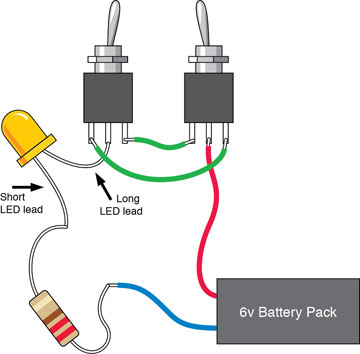
Figure 2-17.
If the LED is on, flipping either of the switches will turn it off. If the LED is off, either of the switches will turn it on. Use alligator clips to attach the wires to each other, and to the switches if your switches don't have screw terminals. Be careful that the clips don't touch each other.
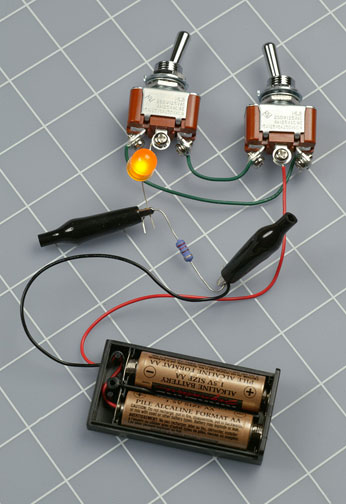
Figure 2-18.
Full-size toggle switches with screw terminals make it easy to hook up this simple circuit.
Tools
If automatic wire strippers (Figure 2-19) don’t grip skinny 22-gauge wire very effectively, try the Ideal brand of wire strippers shown back in Figure 2-4, or use plain and simple wire cutters as shown in Figure 2-20. When using wire cutters, you hold the wire in one hand and apply the tool in your other hand, squeezing the handles with moderate pressure—just enough to bite into the insulation, but not so much that you chop the wire. Pull the wire down while you pull the cutters up, and with a little practice you can rip the insulation off to expose the end of the wire.