Make: Electronics (13 page)
Authors: Charles Platt

Theory
Basic measurements
Electrical potential is measured by adding up the charges on individual electrons. The basic unit is the
coulomb
, equal to the total charge on about 6,250,000,000,000,000,000 electrons.
If you know how many electrons pass through a piece of wire each second, this establishes the flow of electricity, which can be expressed in amperes. In fact 1 ampere can be defined as 1 coulomb per second. Thus:
1 ampere = 1 coulomb/second
= about 6.25 quintillion electrons/second
There’s no way to “see” the number of electrons running through a conductor (Figure 1-76), but there are indirect ways of getting at this information. For instance, when an electron goes running through a wire, it creates a wave of electromagnetic force around it. This force can be measured, and we can calculate the amperage from that. The electric meter installed at your home by the utility company functions on this principle.
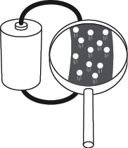
Figure 1-76.
If you could look inside an electric wire with a sufficiently powerful magnifying device, and the wire happened to be carrying 1 ampere of electron flow at the time, you might hope to see about 6.25 quintillion electrons speeding past each second.
If electrons are just moving freely, they aren’t doing any work. If you had a loop of wire of zero resistance, and you kick-started a flow of electrons somehow, they could just go buzzing around forever. (This is what happens inside a superconductor—almost.)
Under everyday conditions, even a copper wire has some resistance. The force that we need to push electrons through it is known as “voltage,” and creates a flow that can create heat, as you saw when you shorted out a battery. (If the wire that you used had zero resistance, the electricity running through it would not have created any heat.) We can use the heat directly, as in an electric stove, or we can use the electrical energy in other ways—to run a motor, for instance. Either way, we are taking energy out of the electrons, to do some work.
One volt can be defined as the amount of pressure that you need to create a flow of 1 ampere, which does 1 watt of work. As previously defined, 1 watt = 1 volt × 1 ampere, but the definition actually originated the other way around:
1 volt = 1 watt/1 ampere
It’s more meaningful this way, because a watt can be defined in nonelectrical terms. Just in case you’re interested, we can work backward through the units of the metric system like this:
1 watt = 1 joule/second
1 joule = a force of 1 newton acting through 1 meter
1 newton = the force required to accelerate 1 kilogram by 1 meter per second, each second
On this basis, the electrical units can all be anchored with observations of mass, time, and the charge on electrons.
Practically Speaking
For practical purposes, an intuitive understanding of electricity can be more useful than the theory. Personally I like the water analogies that have been used for decades in guides to electricity. Figure 1-77 shows a tall tank half full of water, with a hole punched in it near the bottom. Think of the tank as being like a battery. The height of the water is comparable to voltage. The volume of flow through the hole, per second, is comparable to amperage. The smallness of the hole is comparable to resistance. See Figure 1-79 on the next page.
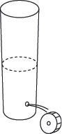
Figure 1-77.
If you want to get work out of a system…
Where’s the wattage in this picture? Suppose we place a little water wheel where it is hit by the flow from the hole. We can attach some machinery to the water wheel. Now the flow is doing some work. (Remember, wattage is a measurement of work.)
Maybe this looks as if we’re getting something for nothing, extracting work from the water wheel without putting any energy back into the system. But remember, the water level in the tank is falling. As soon as I include some helpers hauling the waste water back up to the top of the tank (in Figure 1-78), you see that we have to put work in to get work out.
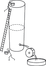
Figure 1-78.
. . . somehow or other you have to put work back into it.
Similarly, a battery may seem to be giving power out without taking anything in, but the chemical reactions inside it are changing pure metals into metallic compounds, and the power we get out of a battery is enabled by this change of state. If it’s a rechargeable battery, we have to push power back into it to reverse the chemical reactions.
Going back to the tank of water, suppose we can’t get enough power out of it to turn the wheel. One answer could be to add more water. The height of the water will create more force. This would be the same as putting two batteries end to end, positive to negative, in series, to double the voltage. See Figure 1-80. As long as the resistance in the circuit remains the same, greater voltage will create more amperage, because amperage = voltage/resistance.
What if we want to run two wheels instead of one? We can punch a second hole in the tank, and the force (voltage) will be the same at each of them. However, the water level in the tank will drop twice as fast. Really, we’d do better to build a second tank, and here again the analogy with a battery is good. If you wire two batteries side by side, in parallel, you get the same voltage, but for twice as long. The two batteries may also be able to deliver more current than if you just used one. See Figure 1-81.
Summing up:
- Two batteries in series deliver twice the voltage.
- Two batteries in parallel can deliver twice the current.
All right, that’s more than enough theory for now. In the next chapter, we’ll continue with some experiments that will build on the foundations of knowledge about electricity, to take us gradually toward gadgets that can be fun and useful.
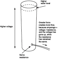
Figure 1-79.
Greater force generates more flow, as long as the resistance remains the same.
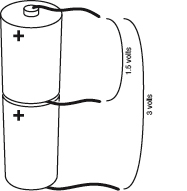
Figure 1-80.
When you place two equal batteries in series, you double the voltage.
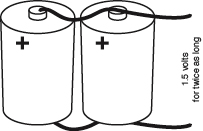
Figure 1-81.
Two equal batteries that are wired in parallel will deliver the same voltage for twice as long as one.
2.
Switching Basics and More
The concept of switching is fundamental in electronics, and I’m not just talking about power switches. By “switching,” I mean using one flow of electricity to switch, or control, another. This is such an important principle that no digital device can exist without it.
Today, switching is mostly done with semiconductors. Before I deal with them, I’ll back up and illustrate the concept by introducing you to relays, which are easier to understand, because you can see what’s going on inside them. And before I get to relays, I’ll deal with everyday on/off switches, which may seem very simple—but we have to nail down the basics.
Also in this chapter, I’ll deal with capacitance, because capacitance and resistance are fundamental to electronic circuits. By the end of the chapter, you should have a basic grounding in electronics and be able to build the noisemaking section of a simple intrusion alarm. This will be your first circuit that does something genuinely useful!
Shopping List: Experiments 6 Through 11
As in the previous shopping list, you should visit the various online suppliers for availability and pricing of components and devices. Manufacturers seldom sell small numbers of parts directly. Check the appendix for a complete list of URLs for all the companies mentioned here.
Devices
- Power supply/universal AC adapter, 3 to 12 volts at 1A (1,000 mA). See Figure 2-1. Part number 273-316 from RadioShack, part PH-62092 by Philips, or similar.
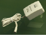
Figure 2-1.
AC adapters of this general type
can supply a variety of voltages, with a
range as wide as 3 to 12 volts. - Breadboard suitable for integrated circuits. Quantity: 1. See Figures 2-2 and 2-3. Part 276-002 from RadioShack, model 383-X1000 made by PSP, part 923252-I by 3M, or similar. A breadboard that has screw terminals mounted beside it will be a little easier to use but more expensive than one that does not have terminals.
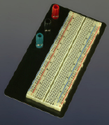
Figure 2-2.
This “breadboard” for quickly constructing electronic circuits has a metal base, and screw terminals for attaching wires from a power supply.
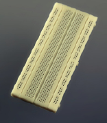
Figure 2-3.
A breadboard without screw terminals is almost as convenient, and is cheaper.
Tools
Wire strippers
Ideal model 45-121 wire strippers for 16- to 26-gauge wire, or similar. See Figure 2-4. (The “gauge” of the wire tells you how thick it is. A higher gauge means a thinner wire. In this book, we will mainly be using thin wire of 20- to 24-gauge.)
You may also consider the Kronus Automatic Wire Strippers, part 64-2981 from RadioShack, or GB Automatic Wire Strippers, part SE-92 from Amazon.com. See Figure 2-5.
The Kronus and GB wire strippers are functionally identical. The advantage of their design is that it enables you to strip insulation from a wire with one hand. But they do not work well on really thin wire.
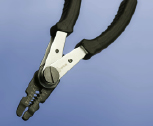
Figure 2-4.
To use these wire strippers, insert a piece of insulated wire in the appropriate-sized hole between the jaws, grip the handles, and pull a section of insulation away. See
page 45
.
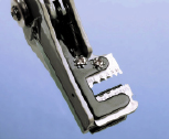
Figure 2-5.
These automatic wire strippers enable one-handed operation, but are not suitable for very small wire diameters. See
page 44
.
Supplies
Hookup wire
Solid-conductor, 22-gauge, minimum 25 feet of each color. See Figure 2-6. Part 278-1221 from RadioShack, catalog item 9948T17 from McMaster-Carr, or check eBay for deals.
It’s easy to buy the wrong kind of wire. You need solid-core wire, which has a single conductor inside the plastic insulation, not stranded, which has multiple, thinner conductors. See Figures 2-7 and 2-8. You’re going to be pushing wires into little holes in a “breadboard,” and stranded wire won’t let you do this. You will also have problems if you buy wire thicker than 22-gauge. Remember: the lower the gauge number, the thicker the wire.
For a little extra money, you can buy an assortment of precut sections of wire, with ends stripped and ready for use. Try catalog item JW-140 (jumper wire assortment) from All Electronics or search eBay for “breadboard wire.” See Figure 2-9.

Figure 2-6.
Using hookup wire with different colors of plastic insulation will help you to distinguish one wire from another in your circuits.
Patch cords
Patch cords are not strictly necessary but very convenient. You don’t want audio or video patch cords, which have a plug on each end; you want wires with alligator clips on each end, also sometimes referred to as “test leads.” Try catalog item 461-1176-ND from Digi-Key or catalog item MTL-10 from All Electronics. See Figure 2-10.
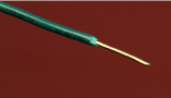
Figure 2-7.
Solid-conductor wire of 22 or 24 gauge is suitable for most of the experiments in this chapter.
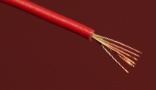
Figure 2-8.
Stranded is more flexible, but cannot be used easily with breadboards.
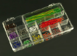
Figure 2-9.
Precut wires with stripped ends can save a lot of time and trouble—if you don’t mind paying a little extra.
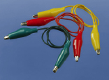
Figure 2-10.
Patch cords, sometimes known as test leads, consist of wires preattached to alligator clips. This is another of those little luxuries that reduces the hassle factor in hobby electronics.