Make: Electronics (75 page)
Authors: Charles Platt

Figure 5-65.
The simple pleasure of picking up a radio signal with ultra-simple components and no additional power.
Figures 5-66 and 5-67 show the completed radio.
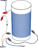
Figure 5-66.
A signal from the antenna can pass through the coil to ground. If the jumper wire is attached to an appropriate tap on the coil, it resonates with the radio signal, just powerfully enough to energize the earphone which is wired in series with a diode.
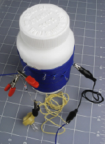
Figure 5-67.
The real-life version of Figure 5-66.
If you’ve managed to follow these instructions (one way or another), it’s time to tune your radio to the nearest station. Move the alligator clip at the end of your patch cord from one tap to another on your coil. Depending on where you live, you may pick up just one station, or several, some of them playing simultaneously.
It may seem that you’re getting something for nothing here, as the earphone is making noise without any source of power. Really, though, there is a source of power: the transmitter located at the radio station. A large amplifier pumps power into the broadcasting tower, modulating a fixed frequency. When the combination of your coil and antenna resonates with that frequency, you’re sucking in just enough voltage and current to energize a high-impedance headphone.
The reason you had to make a good ground connection is that the radio station broadcasts its signal at a voltage relative to ground. The earth completes the circuit between you and the transmitter. For more information on this and other concepts relating to radio, see the upcoming section “Theory: How radio works.”
Enhancements
The higher your antenna is, the better it should work. In my location, this is a major problem, as I live in a desert area without any trees. Still, just stringing the wire out of my window and tethering it (with rope) to the front bumper of my car enabled me to pick up a faint radio signal.
To improve the selectivity of your radio, you can add a variable capacitor, as shown in the following section. This allows you to “tune” the resonance of your circuit more precisely. Variable capacitors are uncommon today, but you can find one at the same specialty source that I recommended for the earphone and the germanium diode: the Scitoys Catalog (
http://www.scitoyscatalog.com
)
.
This source is affiliated with a smart man named Simon Quellan Field, whose site suggests many fun projects that you can pursue at home. One of his clever ideas is to remove the germanium diode from your radio circuit and substitute a low-power LED in series with a 1.5-volt battery. This didn’t work for me, because I live 40 miles from the nearest AM broadcaster. If you’re closer to a transmitter, you may be able to see the LED varying in intensity as the broadcast power runs through it.
Theory
How radio works
When electrical frequencies are very high, the radiation they create has enough energy to travel for miles. This is the principle of radio transmission: A high-frequency voltage is applied to a broadcasting antenna, relative to the ground.
When I say “ground” in this instance, I literally mean the planet beneath us. If you set up a receiving antenna, it can pick up a faint trace of the transmission relative to the ground—as if the earth is one huge conductor. Actually the earth is so large and contains so many electrons, it can function as a common sink, like a gigantic version of the file cabinet that I suggested you should touch to get rid of static electricity in your body before touching a CMOS logic chip.
To make a radio transmitter, I could use a 555 timer chip running at, say, 850 kHz (850,000 cycles per second), and pass this stream of pulses through an amplifier to a transmission tower; if you had some way to block out all the other electromagnetic activity in the air, you could detect my signal and reamplify it.
This was more or less what Marconi (shown in Figure 5-68) was doing in 1901, after he had purchased rights to Edison’s wireless telegraphy patent, although he had to use a primitive spark gap, rather than a 555 timer, to create the oscillations. His transmissions were of limited use, because they had only two states: on or off. You could send Morse code messages, and that was all.
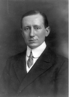
Figure 5-68.
Marconi, the great pioneer of radio (photograph from Wikimedia Commons).
Five years later, the first true audio signal was transmitted by imposing lower audio frequencies on the high-frequency carrier wave. In other words, the audio signal was “added” to the carrier frequency, so that the power of the carrier varied with the peaks and valleys of the audio.
At the receiving end, a very simple combination of a capacitor and a coil detected the carrier frequency out of all the other noise in the electromagnetic spectrum. The values of the capacitor and the coil were chosen so that their circuit would “resonate” at the same frequency as the carrier wave. Figures 5-69 and 5-70 illustrate these concepts.
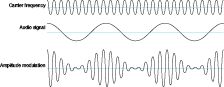
Figure 5-69.
When an audio signal (middle) is combined electronically with a high carrer frequency (top), the result looks something like the compound signal at the bottom. In actuality, the carrier frequency would be much higher compared with the audio frequency, by a radio of perhaps 1,000:1.
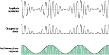
Figure 5-70.
When the compound signal is passed through a diode, only the upper half remains. An earphone cannot react fast enough to reproduce the high carrier frequency, so it “rides” the peaks and thus reproduces the audio frequency.
The schematic in Figure 5-71 shows the simple circuit that you built by wrapping a coil around an empty vitamin bottle. When a positive pulse was received by the antenna, it resonated with the antenna and the coil, provided that the antenna was long enough and the coil was tapped at the appropriate number of turns.
Theory
How radio works (continued)
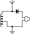
Figure 5-71.
An antenna at the top of the schematic picks up faint electromagnetic radiation from a distant transmitter. The coil at the left side is tapped at intervals so that its resonance can be adjusted to match the carrier frequency of the radio signal. Other frequencies are grounded (at the bottom of the schematic). The diode passes the “top half” of the signal to the earphone at the right, which is incapable of responding fast enough to reproduce the carrier frequency, and thus filters it out, leaving only the audio frequencies that were superimposed on it.
By adding a capacitor, you can tune the circuit. Now an incoming pulse from the transmitter is initially blocked by the self-inductance of the coil, while it charges the capacitor. If an equally negative pulse is received after an interval that is properly synchronized with the values of the coil and the capacitor, it coincides with the capacitor discharging and the coil conducting. In this way, the right frequency of carrier wave makes the circuit resonate in sympathy. At the same time, audio-frequency fluctuations in the strength of the signal are translated into fluctuations in voltage in the circuit.
What happens to other frequencies pulled in by the antenna? The lower ones pass through the coil to ground; the higher ones pass through the capacitor to ground. They are just “thrown away.”
The righthand half of the circuit samples the signal by passing it through a germanium diode and an earphone. The power from the transmitter is just sufficient to vibrate the diaphragm in the earphone, after the diode has subtracted the negative half of the signal.
Look back at the diagram of the amplitude-modulated signal. You’ll see that it fluctuates up and down so rapidly, the earphone cannot possibly keep up with the positive-negative variations—hence the need for the diode. It will remain hesitating at the midpoint between the highs and lows, producing no sound at all. The diode solves this problem by subtracting the lower half of the “audio envelope,” leaving just the positive spikes of voltage. Although these are still very small and rapid, they are now all pushing the diaphragm of the earphone in the same direction, so that it averages them out, approximately reconstructing the original sound wave.
Figure 5-72 shows how the circuit can be enhanced with a variable capacitor, to tune it without needing to tap the coil at intervals.
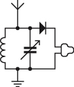
Figure 5-72.
By adding a capacitor to the circuit, its resonance can be tuned more precisely. The diagonal arrow indicates that a variable capacitor is used.
The radio can pull in the stations on the AM (amplitude-modulated) waveband that happen to be most powerful in your area. The waveband ranges from 300 kHz to 3 MHz. If you find yourself interested in radio, your next step could be to build a powered radio using a couple of transistors. Alternatively you could build your own (legal) low-power AM transmitter. There’s an ultra-simple kit available from
http://www.scitoys.com
consisting of just two principal components: a crystal oscillator, and a transformer, shown in Figure 5-73. That’s all it takes.
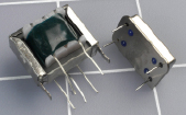
Figure 5-73.
An AM radio transmitter can be made from just two components: a transformer (left) and a crystal oscillator (right), available from http://www.scitoys.com.