Make: Electronics (71 page)
Authors: Charles Platt

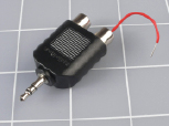
Figure 5-42.
To sample the output from the headphone socket of a music player, you can use this adapter and push the stripped end of a piece of hookup wire into one of the sockets. Then use alligator clips on a jumper wire to connect the audio to your breadboarded circuit. Don’t forget to use an additional jumper wire to connect the outside of the socket to the negative side of the power supply on the breadboard. Because we’re only using one speaker, the amplifier is connected to only one of the stereo outputs from your player. The other is ignored.
The 33K resistor is necessary to protect the amplifier from being overdriven. If you don’t get enough volume using your music player, decrease the 33K value. If the music is too loud and distorted, increase the value. You can also try omitting or increasing the 10K resistor next to it, which is included in an effort to reduce background hum noise.
I’ve shown two switches at the top of the schematic: one to bypass a coil, the other to bypass a capacitor. You can use alligator clips instead, as long as you can easily compare the sound when each of the components is inserted into the circuit.
Figure 5-43 shows a coil consisting of a spool of hookup wire being used. The red and black alligator clips resting loose on top of the shoebox will go to the output from the chip (on pins 2 and 15). There is no polarity; it doesn’t matter which clip goes to which pin.
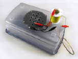
Figure 5-43.
The red and black alligator clips, lying on top of the shoebox, should connect with the output from your amplifier chip. The red jumper wire passes the signal through a coil of hookup wire on its way to the speaker. Note the change in sound when you short out the coil.
Begin by turning the volume control on your music source
all the way down
before you apply power. Don’t be surprised if you hear humming or crackling noises when you activate the amplifier; it will pick up any stray voltages, because in this simple experiment, I haven’t suggested that you should shield the input, and the amplifier circuit can pick up noise, as its wires can act like antennas.
Note that you may also get additional unwanted sound if you use the amplifier on a conductive desktop surface. Remove any aluminum foil or conductive foam for this project.
Make sure that your player is playing music, and slowly turn up its volume control until you hear it. If you don’t hear anything, you’ll have to check for circuit errors.
Now comes the interesting part. Insert the 100-foot spool of hookup wire between one output from the amplifier, and one input of the speaker (it doesn’t matter which one), or if you used switches, open the switch that bypasses the coil. You should find that the music loses all its high-end response. By comparison, if you disconnect the coil and substitute a 10 μF capacitor, you should find that the music sounds “tinny,” meaning that it loses all its low range, leaving only the high frequencies.
You’ve just tested two very simple filters. Here’s what they are doing:
- The coil is a low-pass filter. It passes low frequencies but blocks high frequencies, because brief audio cycles don’t have time to overcome the coil’s self-inductance. A bigger coil eliminates a wider range of frequencies.
- The capacitor is a high-pass filter. It passes high frequencies and blocks low frequencies because longer audio cycles can fill the capacitance, at which point the capacitor stops passing current. A smaller capacitor eliminates a wider ranger of frequencies.
You can go a lot farther into filter design, using complex combinations of coils and capacitors to block frequencies at any point in the audible spectrum. Search online for audio filter schematics—you’ll find hundreds of them.
Crossover Networks
In a traditional audio system, each speaker cabinet contains two drivers—one of them a small speaker called a
tweeter
, which reproduces high frequencies, the other a large speaker known as a
woofer
, which reproduces low frequencies. (Modern systems often remove the woofer and place it in a separate box of its own that can be positioned almost anywhere, because the human ear has difficulty sensing the direction of low-frequency sounds.)
The schematic that you just looked at and may have constructed is known as a “crossover network,” and truly hardcore audiophiles have been known make their own (especially for use in car systems) to go with speakers of their choice in cabinets that they design and build themselves.
If you want to make a crossover network, you should use high-quality polyester capacitors (which have no polarity, last longer than electrolytics, and are better made) and a coil that has the right number of turns of wire and is the right size to cut high frequencies at the appropriate point. Figure 5-44 shows a polyester capacitor.
Figure 5-45 shows an audio crossover coil that I bought on eBay for $6. I was curious to find out what was inside it, so I bought two of them, and took one apart.
First I peeled away the black vinyl tape that enclosed the coil. Inside was some typical magnet wire—copper wire thinly coated with shellac or semitransparent plastic, as shown in Figure 5-46. I unwound the wire and counted the number of turns. Then I measured the length of the wire, and finally used a micrometer to measure the diameter of the wire, after which I checked online to find a conversion from the diameter in mils (1/1,000 of an inch) to American wire gauge.
As for the spool, it was plain plastic with an air core—no iron or ferrite rod in the center. Figure 5-47 shows the spool and the wire.
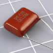
Figure 5-44.
Some nonelectrolytic capacitors have no polarity, such as this high-quality polyester film capacitor. However, they tend to be much more expensive, and are hard to find in values higher than 10 μF.
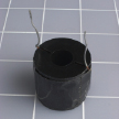
Figure 5-45.
What exotic components may we find inside this high-end audio component that’s used with a subwoofer to block high frequencies?
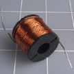
Figure 5-46.
The black tape is removed, revealing a coil of magnet wire.
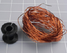
Figure 5-47.
The audio crossover coil consists of a plastic spool and some wire. Nothing more.
So here’s the specification for this particular coil in an audio crossover network. Forty feet of 20-gauge copper magnet wire, wrapped in 200 turns around a spool of 1/16–inch-thick plastic with a hub measuring 7/8 inch in length between the flanges and 1/2-inch external diameter. Total retail cost of materials if purchased separately: probably about $1, assuming you can find or make a spool of the appropriate size.
Conclusion: there’s a lot of mystique attached to audio components. They are frequently overpriced, and you can make your own coil if you start with these parameters and adjust them to suit yourself.
Suppose you want to put some thumping bass speakers into your car. Could you build your own filter so that they only reproduce the low frequencies? Absolutely—you just need to wind a coil, adding more turns until it cuts as much of the high frequencies as you choose. Just make sure the wire is heavy enough so that it won’t overheat when you push 100 or more audio watts through it.
Here’s another project to think about: a color organ. You can tap into the output from your stereo and use filters to divide audio frequencies into three sections, each of which drives a separate set of colored LEDs. The red LEDs will flash in response to bass tones, yellow LEDs in response to the mid-range, and green LEDs in response to high frequencies (or whatever colors you prefer). You can put signal diodes in series with the LEDs to rectify the alternating current, and series resistors to limit the voltage across the LEDs to, say, 2.5 volts (when the music volume is turned all the way up). You’ll use your meter to check the current passing through each resistor, and multiply that number by the voltage drop across the resistor, to find the wattage that it’s handling, to make sure the resistor is capable of dissipating that much power without burning out.