Make: Electronics (21 page)
Authors: Charles Platt

Background
Michael Faraday and capacitors
The earliest capacitors consisted of two metal plates with a very small gap between them. The principle of the thing was simple:
- If one plate was connected to a positive source, the positive charges attracted negative charges onto the other plate.
- If one plate was connected to a negative source, the negative charges attracted positive charges onto the other plate.
Figures 2-67 and 2-68, shown previously, convey the basic idea.
The electrical storage capacity of a capacitor is known as its
capacitance
, and is measured in farads, named after Michael Faraday (Figure 2-71), another of the pantheon of electrical pioneers. He was an English chemist and physicist who lived from 1791 to 1867.
Although Faraday was relatively uneducated and had little knowledge of mathematics, he had an opportunity to read a wide variety of books while working for seven years as a bookbinder’s apprentice, and thus was able to educate himself. Also, he lived at a time when relatively simple experiments could reveal fundamental properties of electricity. Thus he made major discoveries including electromagnetic induction, which led to the development of electric motors. He also discovered that magnetism could affect rays of light.
His work earned him numerous honors, and his picture was printed on English 20-pound bank notes from 1991 through 2001.

Figure 2-71.
Michael Faraday
Breadboarding the Circuit
I promised to free you in time from the frustrations of alligator clips, and that time has come. Please turn your attention to the block of plastic with lots of little holes in it that I asked you to buy. For reasons that I do not know, this is called a
breadboard
. When you plug components into the holes, hidden metal strips inside the breadboard connect the components for you, allowing you to set up a circuit, test it, and modify it very easily. Afterward you can pull the components off the breadboard and put them away for future experiments.
Without a doubt, breadboarding is the most convenient way to test something before you decide whether you want to keep it.
Almost all breadboards are designed to be compatible with integrated circuit chips (which we will be using in
Chapter 4
of this book). The chip straddles an empty channel in the center of the breadboard with rows of little holes either side—usually five holes per row. You insert other components into these holes.
In addition, the breadboard should have columns of holes running down each side. These are used to distribute positive and negative power.
Take a look at Figures 2-72 and 2-73, which show the upper part of a typical breadboard seen from above, and the same breadboard seen as if with X-ray vision, showing the metal strips that are embedded behind the holes.

Figure 2-72.
A typical breadboard. You can plug components into the holes to test a circuit very quickly.
Figure 2-73.
This X-ray-vision view of the breadboard reveals the copper strips that are embedded in it. The strips conduct electricity from one component to another.
Important note: some breadboards divide each vertical column of holes, on the left and the right, into two separate upper and lower sections. Use your meter’s continuity testing feature to find out if your breadboard conducts power along its full length, and add jumper wires to link the upper and lower half of the breadboard if necessary.
Figure 2-74 shows how you can use the breadboard to replicate your oscillating relay circuit. To make this work, you need to apply the positive and negative power from your AC adapter. Because the wire from your AC adapter is almost certainly stranded, you’ll have difficulty pushing it into the little holes. A way around this is to set up a couple of pieces of bare 22-gauge wire, and use them as terminals to which you clip the wire from the adapter, as in Figure 2-75. (Yes, you still need just a couple of alligator clips for this purpose.) Alternatively, you can use a breadboard with power terminals built into it, which is more convenient.
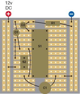
Figure 2-74.
If you place the components on your breadboard in the positions shown, they will create the same circuit that you built from wire and alligator clips in
Experiment 8
. Component values:
D1, D2: Light-emitting diodes
S1: DPDT relay
S2: SPST momentary switch
C1: Electrolytic capacitor, 1,000 µF
R1: Resistor, 680Ω minimum
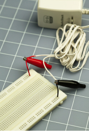
Figure 2-75.
If your breadboard doesn’t have screw terminals, insert two short pieces of solid-core wire with stripped ends and then attach the stranded wires from the adapter using alligator clips.
You’ll need some more 22-gauge wire, or some precut hookup wire, to supply the power to your components, which are plugged into the breadboard as shown in Figures 2-76 and 2-77. If you get all the connections right, the circuit should function the same way as before.
The geometry of the metal connecting strips in the breadboard often forces you to connect components in a roundabout way. The pushbutton, for instance, supplies power to the pole of the relay but cannot be connected directly opposite, because there isn’t room for it.
Remember that the strips inside the breadboard that don’t have any wires or components plugged into them are irrelevant; they don’t do anything.
I’ll include some suggested breadboard layouts for circuits as you continue through this book, but eventually you’ll have to start figuring out breadboard layouts for yourself, as this is an essential part of hobby electronics.
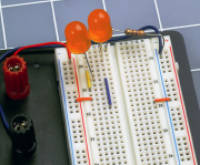
Figure 2-76.
Two oversized LEDs, one resistor, and the necessary jumper wires have been added to the breadboard.
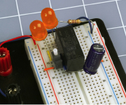
Figure 2-77.
Now the pushbutton, relay, and capacitor have been added to complete the circuit shown in the diagram and the schematic. When the pushbutton is pressed, the relay oscillates and the LEDs flash.
Experiment 9: Time and Capacitors
You will need:
- AC adapter, breadboard, wire, wire cutters, and strippers.
- Multimeter.
- Pushbutton, SPST. Quantity: 1.
- Resistors and electrolytic capacitors, assorted.
In
Experiment 8
, when you put a capacitor in parallel with the coil of the relay, the capacitor charged almost instantly before discharging itself through the relay coil. If you add a resistor in series with a capacitor, the capacitor will take longer to charge. By making a capacitor take longer to charge, you can measure time, which is a very important concept.
Clean the components off your breadboard and use it to set up the very simple circuit shown in Figure 2-78, where C1 is a 1,000 µF capacitor, R1 is a 100K resistor, R2 is a 100Ω resistor, and S1 is the pushbutton that you used previously. Set your meter to measure volts DC, place the probes around the capacitor, and hold down the pushbutton. You should see the meter counting upward as the voltage accumulates on the capacitor. (This is easier with a meter that doesn’t have autoranging, because you won’t have to wait while the meter figures out which range to apply.) Resistor R1 slows the charging time for the capacitor.