Make: Electronics (27 page)
Authors: Charles Platt

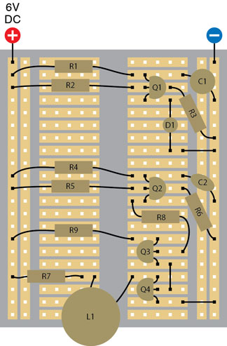
Figure 2-109.
Q4 is another 2N2222 transistor that further amplifies the signal. It receives power through R9: 2.2K.
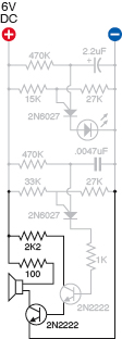
Figure 2-110.
This schematic is comparable with the component layout in Figure 2-109.
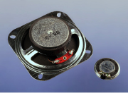
Figure 2-111.
The 2N2222 transistor is quite capable of driving a 3-inch loudspeaker, which will create much better sound than a 1-inch speaker.
Step 4: Pulsed Output
If you wanted to use this audio signal as some kind of an alarm, a steady droning noise is not very satisfactory. A pulsing output would be a much better attention-getter.
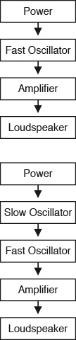
Figure 2-112.
Top: The basic functions of the noisemaking oscillator circuit shown as a block diagram. Bottom: The same functions with a slow oscillator added to control the fast oscillator.
Well, the first section of the circuit that you assembled created a pulsing signal about twice per second. You used it to flash an LED. Maybe we can get rid of the LED and feed the output from the first section to the second section. The lower block diagram in Figure 2-112 explains this concept.
Can it really be that simple? Well, yes and no. The trick is to make the output from the first section compatible with the input to the second section. If you simply connect a wire from the cathode of the first PUT to the anode of the second PUT, that’s not going to work, because the second PUT is already oscillating nicely between low and high voltage, about 1,000 times each second. Add more voltage, and you will disrupt the balance that enables oscillation.
However, remember that the voltage on the gate of a PUT affects its threshold for conducting electricity. Maybe if we connect the output from Q1 to the gate of Q2, we’ll be able to adjust that threshold automatically. The voltage still has to be in a range that the PUT finds acceptable, though. We can try various resistors to see which one works well.
This sounds like trial and error—and that’s exactly what it is. Doing the math to predict the behavior of a circuit like this is far too complicated—for me, anyway. I just looked at the manufacturer’s data sheet, saw the range of resistor values that the PUT would tolerate, and chose one that seemed as if it should work.
If you remove the LED and substitute R10 as shown in the breadboard diagram in Figure 2-113, you’ll find that the fluctuating output from Q1 makes Q2 emit a two-tone signal. This is more interesting, but still not what I want. I’m thinking that if I make the pulses out of Q1 less abrupt, the result could be better, and the way to smooth a pulsing output is to hook up another capacitor that will charge at the beginning of each pulse and then release its charge at the end of each pulse. This is the function of C3 in Figure 2-114, and it completes the circuit so that it makes a whooping sound almost like a “real” alarm.
If you don’t get any audio output, check your wiring very carefully. It’s easy to make a wrong connection on the breadboard, especially between the three legs of each transistor. Use your meter, set to DC volts, to check that each section of the circuit has a positive voltage relative to the negative side of the power supply.
Figure 2-115 shows how your circuit should actually look on the breadboard.
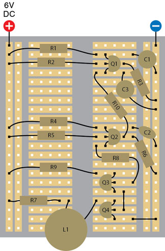
Figure 2-113.
R10 connects the slow-running oscillator at the top of the breadboard to the gate of Q2, the PUT in the middle of the breadboard. This modulates the audio oscillator, with addition of a smoothing capacitor.
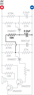
Figure 2-114.
This schematic shows the same circuit as in Figure 2-113:
R10: 10K
C3: 2.2 μF
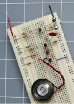
Figure 2-115.
This photograph shows the complete alarm-audio circuit on a breadboard.
Tweaking it
There’s still a lot of room for creativity here:
- Adjust the frequency of the sound: Use a smaller or larger capacitor instead of C2 (half or twice the current value). Use a smaller or larger value for R5.
- Adjust the pulsing feature: Use a smaller or larger capacitor instead of C1 (half or twice the current value). Use a smaller or larger value for R2.
- General performance adjustments: try a larger value for R1. Try smaller or larger values for C3.
- Try running the circuit at 7.5 volts, 10 volts, and 12 volts.
The circuits in this book are suggested as only a starting point. You should always try to tweak them to make them your own. As long as you follow the general rule of protecting transistors and LEDs with resistors, and respecting their requirements for positive and negative voltage, you’re unlikely to burn them out. Of course, accidents will happen—I myself tend to be careless, and fried a couple of LEDs while working on this circuit, just because I connected them the wrong way around.
Step 5: Enhancements
A noisemaking circuit is just the output of an alarm. You would need several enhancements to make it useful:
1.
Some kind of an intrusion sensor. Maybe magnetic switches for windows and doors?
2.
A way to start the sound if any one of the sensors is triggered. The way this is usually done is to run a very small but constant current through all of the switches in series. If any one switch opens, or if the wire itself is broken, this interrupts the current, which starts the alarm. You could make this happen with a double-throw relay, keeping the relay energized all the time until the circuit is broken, at which point, the relay relaxes, opening one pair of contacts and closing the other pair, which can send power to the noisemaker.
The trouble is that a relay draws significant power while it’s energized, and it also tends to get hot. I want my alarm system to draw very little current while it’s in “ready” mode, so that it can be powered by a battery. Alarm systems should never depend entirely on AC house current.
If we don’t use a relay, can we use a transistor to switch on the rest of the circuit when the power is interrupted? Absolutely; in fact, one transistor will do it.
3.
But how do we arm the alarm in the first place? Really, we need a three-step procedure. First, check a little light that comes on when all the doors and windows are closed. Second, press a button that starts a 30-second countdown, giving you time to leave, if that’s what you want to do. And third, after 30 seconds, the alarm arms itself.
4.
If the alarm is triggered, what then? If someone forces open a window, should the alarm stop sounding as soon as the window is closed again? No, the alarm should lock itself on, until you turn it off.
5.
How do you turn it off? Some kind of secret-code keypad would be good.
6.
But to avoid driving everyone crazy if the alarm is triggered when you’re not there, it should eventually stop itself, perhaps after about 10 minutes. At that point it should remain quiet but should light an LED to tell you what happened. You can then press a reset button to switch off the LED.