DIY Projects for the Self-Sufficient Homeowner: 25 Ways to Build a Self-Reliant Lifestyle (38 page)
Authors: Betsy Matheson
Tags: #Non-Fiction

The mounting stand
for the PV panel is constructed from metal U-channel and pre-bent fasteners. Electrical connections to the power distribution system are made inside the garage.

The stand components
are held together with bolts and spring-loaded fasteners. The 45° and 90° connectors are manufactured specifically for use with this Unistrut system.

Connections for the feed wires
that carry current from the collector are made inside an electrical box mounted on the back of the collector panel.
First, install two tracks of U-channel on the roof, parallel to the long edges of the panel. Attach the channels to the roof deck use the mounting hardware designed for your mounting system. Mount two 30° beam clamps onto the U-channel tracks to hold the panel at the best angle for maximum sunlight exposure.
Determine the location of the wire leads that penetrate the roof and will connect to the charge controller and battery. Mark the position for the leads onto the roof and use a 7/8" drill bit to bore an opening in the roof at this mark. Install a roof flange with a rubber boot over the opening and insert a section of 3/4"-dia. PVC conduit into the boot. Seal all casing connections with silicon caulk.
Attach the panel to the stand beam clamps and thread the lead wires through the PVC conduit leading into the structure. Tighten all bolts securely. Check that the panel fits tightly into the clamps and does not move even slightly when agitated.
Make Interior Wiring Connections
Mount a junction box inside the building directly underneath the PVC conduit and wiring entry point, attaching it to a rafter or truss. Secure the box to the PVC conduit and seal with silicon caulk. Feed the lead wires from the PV panel into the junction box.
On a wall at roughly switch height, install a DC disconnect switch in a junction box. The disconnect switch allows you to shut off the flow of electrical current from the solar panel. Attach a junction box to enclose the DC disconnect to a wall stud near the battery and charge controller location. Run flexible metal conduit along the rafters or trusses and wall studs from the ceiling junction box to the DC disconnect box.
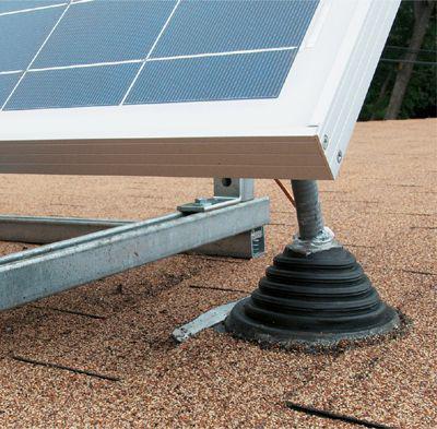
An EPDM rubber boot
seals off the opening where the PVC conduit carrying the feed wires penetrates the roof.
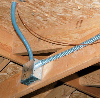
The feed wires
from the collector are fed into a junction box inside the structure where connections to the power distribution equipment are made.
Attach a junction box beneath the DC disconnect box to enclose the charge controller. Connect the controller to the DC disconnect box with flexible metal conduit. Install the charge controller inside the box. About 2" away from the charge controller, mount a touch-safe fuse holder with a 10-amp “catastrophe” fuse as well.
Determine the placement of the battery and then decide where you will position the charge controller and DC disconnect nearby. The battery should be placed at least 18"off the floor in a well-ventilated area, where it won’t be agitated by everyday activity.
Build the battery shelving. Securely attach the plastic battery casing to a plywood shelf with wood screws.
Set up grounding protection by pounding an 8-ft. long ground rod into the earth outside the building, about 1 foot from the wall on the opposite side of the charge controller. Leave about 2" of the rod sticking out of the ground. Attach a ground rod clamp to the top of the rod. Run a 6-gauge THWN wire from the ground rod to the bottom of the DC disconnect box. Cut the wire, leaving about 8" of length inside the DC disconnect box.
Run wiring from the disconnect switch to the ceiling junction box. Thread 6-gauge wire through the PVC conduit and attach it directly to a metal component of the PV panel. This wire will run down to the grounding rod for lightning protection.
Attach the two 14-gauge wires to the two terminals labeled “line” on the top of the DC disconnect switch. Route two more 14-gauge wires from the bottom of the DC disconnect terminals into the junction box and connect to the “Solar Panel In” terminals on the charge controller. The black wire should connect to the negative terminal and the red to the positive. Screw a ground pigtail into the DC disconnect box and splice together both 6-gauge wires and the ground tail into a red wire connector.
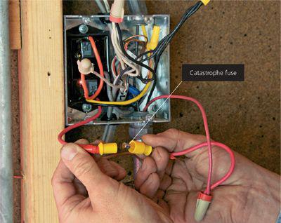
A 10-amp “catastrophe fuse”
is inserted in the incoming current line to protect the fixtures from damaging power surges, most often the result of a lightning strike.
Connect the charge controller to the battery. Run a 14-gauge wire from the charge controller output that goes to the battery to the line side of the touch-safe fuse. From the load side of the touch-safe fuse holder, run 14-gauge wire through the heavy-duty cable leading to the positive battery terminal location. Crimp the end to the eyelets of the battery casing. Crimp the negative battery terminal wire to the battery casing and route the wire through the second cable into another hole in the bottom of the charge controller junction box and connect to the charge controller at the designated location.
Install the lighting fixtures and hook them up to the power source with UF cable.
Make sure the disconnect switch is in the off position. Attach the crimped ends of the lead wires to the battery terminals and put the cover on the battery. At this point, label all wires and seek approval from your local building inspector. Connect the panel to the circuit. To stop the power flowing from the panel, cover it temporarily but securely with an opaque bag or blanket. Attach the black wire from the PV module to the negative lead and the red wire from the panel to the positive lead with yellow wire nuts. Fold the wires into the box and secure the cover onto the box. Remove the bag from the panel and turn the DC disconnect switch on to complete the circuit.
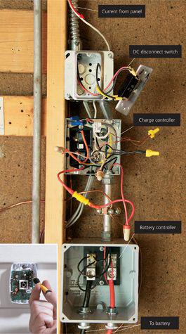
The electrical components
of the power processing system are wired in series through electrical boxes mounted inside the structure. The principal components include the disconnect switch (top box), a charge controller (middle box), and a battery controller (bottom box). An optional motion sensor (inset) triggers the lights.
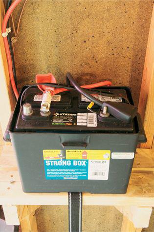
The storage battery
for the 12-volt system should be rated for three days of autonomous usage. Mount the battery in a sturdy plastic case that’s at least 18 in. above ground.

