Read Microsoft Visual C# 2005 Express Edition: Build a Program Now! Online
Authors: Patrice Pelland
Tags: #General, #Computers, #C♯ (Computer program language), #Programming Languages, #C#, #Microsoft .NET Framework, #Computer Books: Languages, #Computer Graphics, #Application software, #C# (Computer program language), #Programming, #Microsoft Visual C# .NET, #Microsoft Visual C♯ .NET, #Electronic books, #Game Programming & Design, #Computing: Professional & Programming, #C (Computer program language), #Computers - Languages, #Programming Languages - C#, #Programming & scripting languages: general
Microsoft Visual C# 2005 Express Edition: Build a Program Now! (32 page)

To add another column, click in the row under the ColorID column name. Add the two remaining col4
As a reminder, when a column is
umns based on the diagram shown in Figure 8-2. You can set the size of the ColorName nvarchar to
an identity, SQL Server automati-
30, by typing in the Data Type field. When done, your table should look like the one shown in Figure 8-6.
cally generates a new number each
time a row is created in a table.
Figure 8-6
It starts at the value indicated by
Table Designer with all of the columns for the Color table
the Identity Seed property and
increases in increments by the
value indicated by the Identity
Increment property.
Now that you’re done with the design, you need to add the table to the database. To do this, you 5 need to save the table. Click the
Save
icon or press
Ctrl+S
. When the Choose Name dialog box appears, as shown in Figure 8-7, name your table
Color
and then click
OK
.
Figure 8-7
In the Table Designer, the little
The Choose Name dialog box showing the Color table name
black triangle indicates the cur-
rent row.
Expand the
Tables
folder in the Database Explorer to view the list of existing tables in the database; 6 the new Color table should appear. When you expand the
Color
table to view the list of columns, all three columns that you just created should appear, as shown in Figure 8-8. 7 Close the Color table in the Table Designer by clicking the
X
near the Solution Explorer. Click the
Save All
icon in the toolbar to save your project. Make sure the project name is CarTracker
Figure 8-8
8
Database Explorer with the Tables
and click the
Save
button.
folder and Color table expanded
Before creating other tables, read this step completely. Now that you have the knowledge to create a 9
table, create all remaining tables (ColorType, Make, and Listing) using the same techniques you’ve just
Whenever you click on a column
learned. Make sure that all tables and
all
of
their columns are recreated exactly the same way in your tables
name in the Database Explorer,
as shown in Figure 8-2. Don’t worry about establishing the relationships, for you’ll create those in the fol
you’ll see the properties listed
lowing exercises. Between each table creation, save your new table immediately and make sure it appears in
in the Properties window. This is
the Database Explorer. Then close the table in the designer surface as shown earlier in step 7 of this section.
the same Properties window that
you’ve been using with one minor
difference: it is a read-only view
and therefore does not let you
modify information.
140
Microsoft Visual C# 2005 Express Edition: Build a Program Now!
C08622299.indd 140
C08622299.indd 140
10/24/05 4:02:35 PM
10/24/05 4:02:35 PM
Creating Relationships Between the Tables
You have created tables, but they don’t have any relationships. You’ll now add those relationships and make sure your database has data integrity to cover the basis of orphaned rows. Like many other elements in Visual C# 2005 Express Edition, there’s more than one way to create those relationships. One is more visual than the other, and you’ll start with this more visual approach so as to stay focused on the main idea of the book, which is being productive.
Before you’re able to create the relationships visually, there is a prerequisite to add to your project: a database diagram. It might not look exactly as the one shown in Figure 8-2, but it will be similar.
TO CREATE RELATIONSHIPS BETWEEN TABLES
Go to the Database Explorer and right-click the
Database Diagrams
node located above the 1 Tables node. Select
Add New Diagram
. A dialog box will appear indicating that SQL Server 2005
Express Edition doesn’t have all of the database objects it needs if you want to create database diagrams. Click
Yes
to have SQL Server create the components it needs to obtain a database diagram. When it’s 2 done creating, you should be asked which tables you want to add to your diagram in the Add Table dialog box.
Depending on your resolution, the
view might be tight. If you want
Select all of the tables you created and then click
Add
. It should take less than a minute for your dia
to view more of the diagram, you
3 gram to appear. Click the
Close
button to indicate to Visual Studio that you have all the tables you need.
might need to unpin or close some
windows, such as the Solution
Explorer or the Properties window;
Click the
Save All
button or press
Ctrl+Shift+S
. You’ll be asked to save your diagram and choose a
you can return these items to your
4
screen by going to the View menu
name. Name your diagram
CarTrackerDiagram
.
and selecting Solution Explorer or
the Properties window. You can
also change the zoom value by
If you don’t see your database diagram, first go to your
Database Diagrams
node, expand it, and then 5
changing the value in the Zoom
open the diagram by double-clicking on it. You should see the designer surface with all of your tables.
drop-down list.
Chapter 8: Managing the Data
141
C08622299.indd 141
C08622299.indd 141
10/24/05 4:02:36 PM
10/24/05 4:02:36 PM
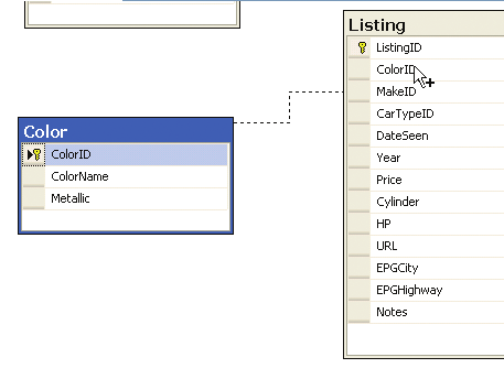
Let’s focus on one relationship that we need to create. When you look at Figure 8-2, you’ll see that the ColorID column is present in the Listing table because there’s a relation to the Color table. The line between both tables is a foreign key (FK) relationship. You need to have this relationship established or otherwise you’ll have orphaned nodes in the Listing table whenever a Color row is deleted. This means that you have to establish a relationship between the primary key table and the foreign key table. In this case, it means you need to create a relationship from the Color table toward the Listing table. 6 In the database diagram, click on
ColorID
in the Color table where you see the small yellow key. Look at Figure 8-9 to see where you should be at the end of this manipulation. Hold the left button 7 down and drag
ColorID
toward the Listing table; you should see a line appear as you drag. Align
Figure 8-9
Creating the foreign key relationship
your mouse cursor so that it’s over the column with which you want to create the relationship—in your
between the CarType and Car tables
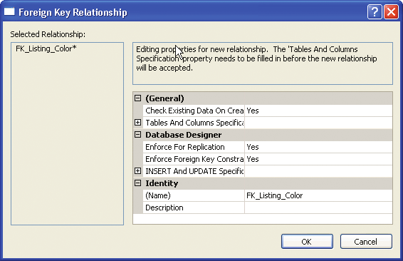
case, over the ColorID field in the Listing table. When you see a small + appear, then drop it. If you correctly selected and released the mouse once you were over ColorID
8 in the Color table, you should see a Tables and Columns dialog box that asks you to confirm the creation of the FK relationship. It’s important for each table that ColorID is the column name that appears to link both tables in that dialog box. If the primary key and foreign key tables are correct and the selected column names are correct, then click the
OK
button.
You should then see the Foreign Key Relationship dialog box shown in
9 Figure 8-10.
Figure 8-10
Foreign Key Relationship dialog box for
the Listing to Color tables
142
Microsoft Visual C# 2005 Express Edition: Build a Program Now!
C08622299.indd 142
C08622299.indd 142
10/24/05 4:02:36 PM
10/24/05 4:02:36 PM

10 Although you can change some properties within this dialog box, just click
OK
for now. See
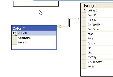
Figure 8-11 to view the diagram with the new relationship created.
To reinforce the concept of estab-
lishing relationships between
Figure 8-11
tables, let me give you another
Modified diagram showing the new FK relationship
way of looking at the relationship
between the Listing and Color tables
in this exercise. There are two
reasons why the ColorID column is
in the Listing table as an FK. The
first reason is that it is used for a
normalization and design principle
because you don’t want to have
duplicate data. The second reason
is that it is used for data integrity
reasons and, more specifically,
for the orphaned rows problem.
Let’s look at it with some sample
data. Suppose there is a Color row
called Dark Blue and the Listing
table contains six different ad def-
initions that are Dark Blue. If you
remove the Dark Blue color from
the Color table, it would mean
that those six ads would have
orphaned data. That is why you
The first thing to note on the diagram is the infinity symbol
located close to the Listing table and the yel
created a foreign key relationship:
low key located close to the Color table. The infinity symbol on the Listing table indicates the table’s cardinal
to make sure that if an application
ity. It indicates that, in this relationship, the Listing table can contain many rows with information coming from
or a user tries to remove data in